I’ve recently had the opportunity through my day job to make a lot of use of an electric car that was not my own. However this presented the inconvenience that I couldn’t charge it on my own home wallbox in the garage since my wallbox has the older Type 1 5-pin connector to suit my own car, but the borrowed car has the more modern Type 2 7-pin connector. If you were buying a wallbox the obvious solution to charging vehicles of both types is a wallbox with a Type 2 socket, however I didn’t want to go down the new wallbox route as I wanted to retain my existing smart controls.
I couldn’t add a socket to my existing wallbox due to packaging constraints (where would I install the socket) and my unsuitable protocol controller (protocol controllers for socketed wallboxes are more complex as they need to decode cable current rating and operate a solenoid). Thus I decided to go down the two outlet cables route as the lowest cost solution given that I already had the cable. My outlay was limited to a relay to switch the power to the second cable, and a switch to decide which cable to use. Use of two relays ensures that only one outlet is live at a time, as there would be a risk of touching the exposed contacts of whichever cable was not in use.
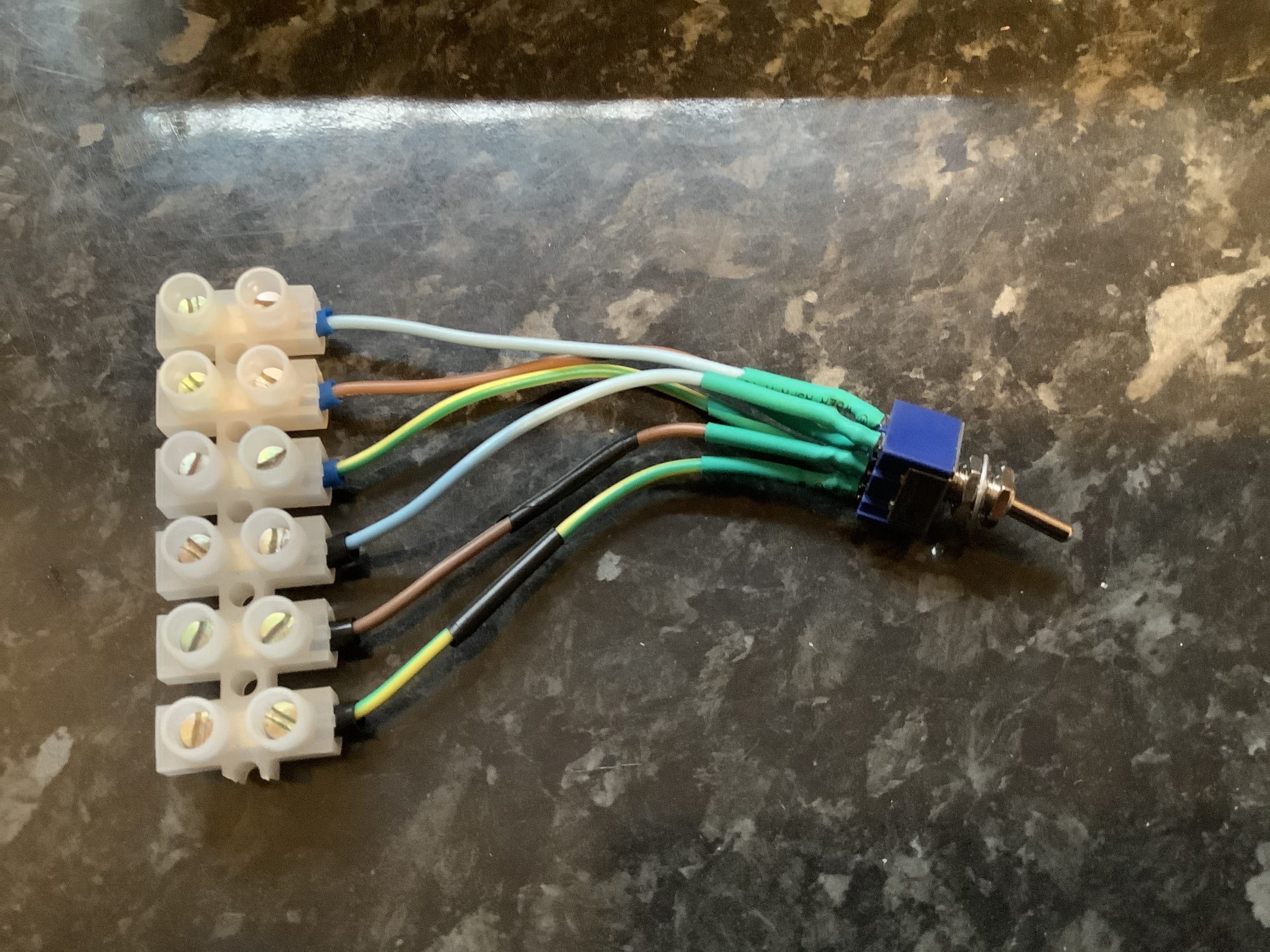
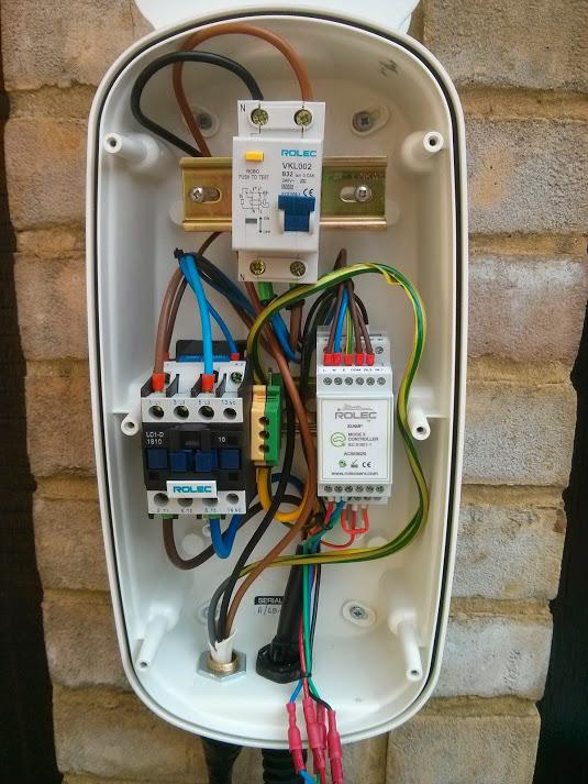
Double Pole Double Throw (DPDT) switch with terminals.
The switch sits between the protocol controller and the relays. One side of the switch directs the relay output of the protocol controller to enable either the original relay for the Type 1 connector or the new relay for the Type 2 connector, while the second side of the switch connects the corresponding control pilot to the protocol controller. The control pilot handles the communication with the vehicle for things like current limits and handshakes.
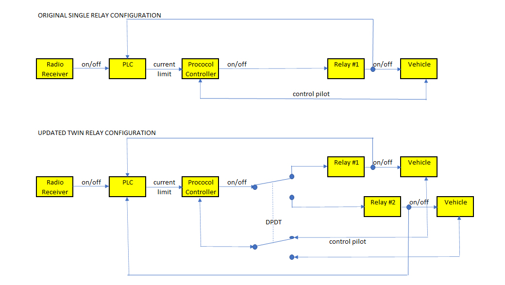
Comparison of charger block diagrams
The open/closed status of each relay is also fed back to the Programmable Logic Controller (PLC) that sets the variable maximum current limit (off, 6, 10 or 16 Amps). The PLC had plenty of spare inputs for the connection to the new relay. Some small software changes were required so that the PLC respond to inputs from both relays (generally either relay #1 or relay #2 is on, or both relay #1 and relay #2 are off).
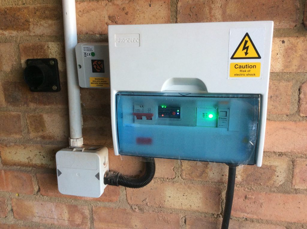
Updated wallbox with second relay to far right and second exit cable to right lower.
From left to right:
2 slots – double pole isolation switch
4 slots – Programmable Logic Controller (PLC)
2 slots – protocol controller
1 slot – original relay for Type 1 / J1772 connector and cable
1 slot – new relay for Type 2 connector and cable
in side panel – DPDT switch
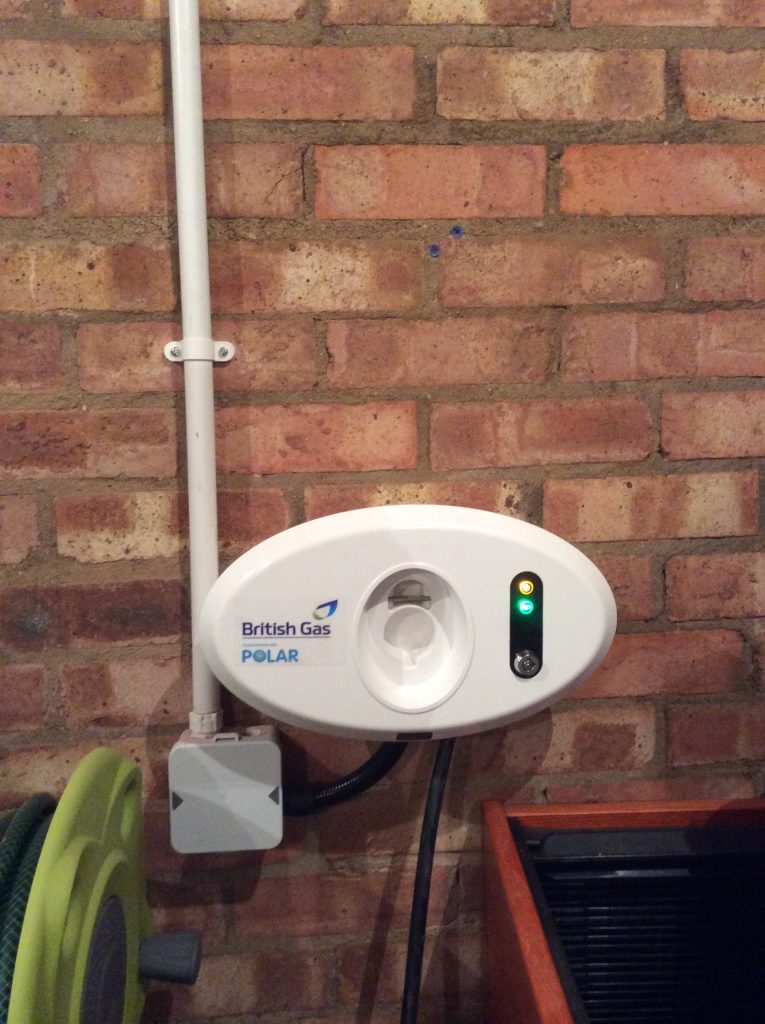
The resulting wallbox has demonstrated its capability to charge vehicles with either Type 1 or Type 2 inlets, responding to tariff-based on/off signals from my HEMS or surplus solar signals from my ImmerSUN.
As we look to install a second electric vehicle charger that becomes a challenge for the electrical supply to our home which is limited to 60 Amps. I recently saw a page online by which our DNO (District Network Operator) – UKPN – could be requested to install an uprated fuse.
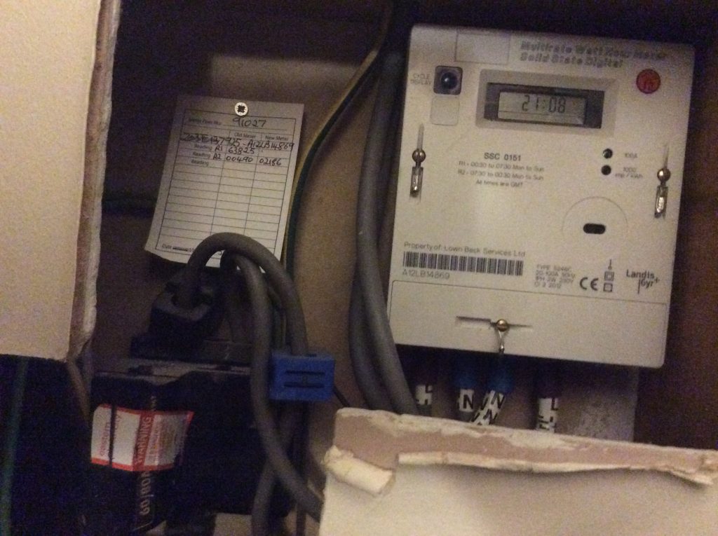
60 Amp cutout and Economy 7 meter
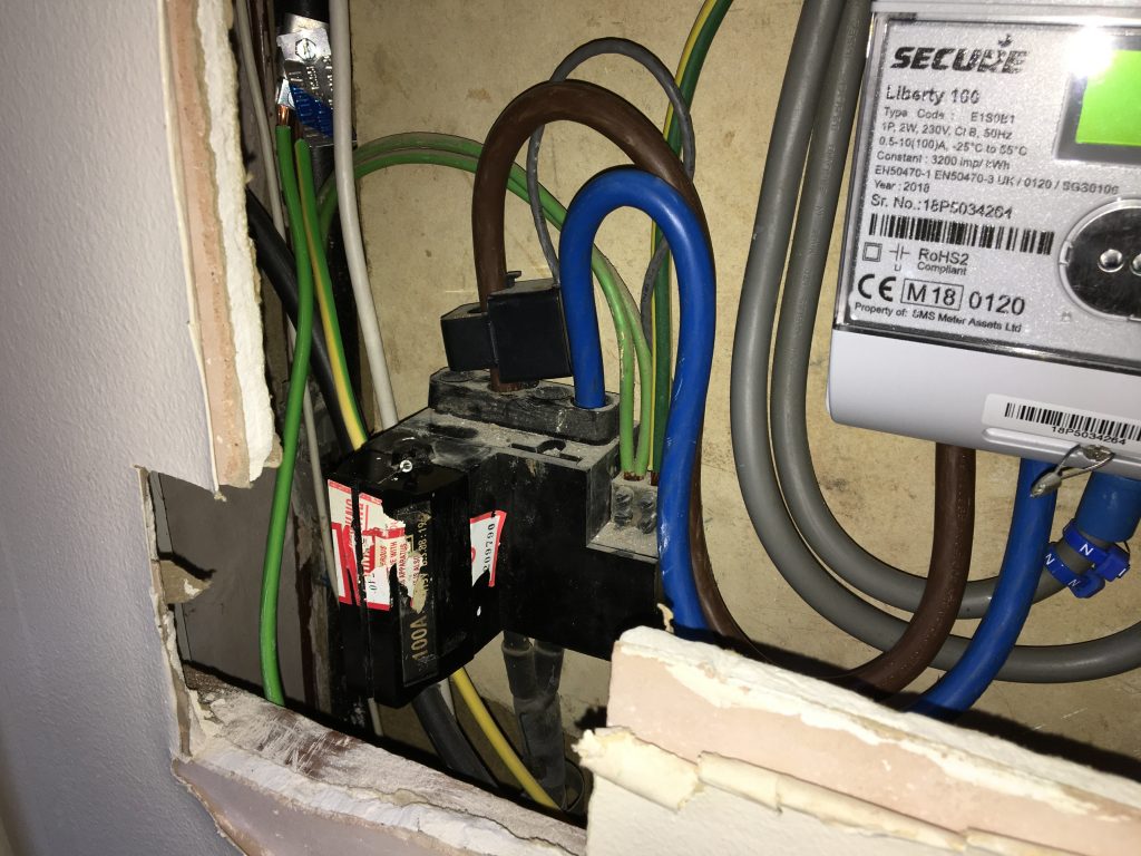
100 Amp cutout and Smart Meter
A comparison of cutouts and meters
(Some readers may be curious regarding the irregular size of the hole around the cutout and meter. When we looked around the house I recall reflecting upon the fact that I didn’t know where the meters and consumer unit were. The mystery was explained when we moved in and these items were found to be behind a false wall in what is now my study having previously been concealed by pictures. We continued the practice by buying pictures to conceal three holes in the wall (now four) covering: electricity meter, gas meter and consumer unit (adding generation meter and isolator for solar panels).)
I’m delighted to report how smoothly the change went. I was advised that it might be the case that the work could not proceed on a first visit, and that it might be necessary for my electricity supplier to update meter and/or cables from meter to consumer unit; but the installation proceeded on the first visit with not only the cutout changed from 60 to 100 Amps but also the cables between the cutout and the meter renewed. All of this at a price of precisely nothing.
I had been reasonably confident in the meter as that had been renewed almost exactly two years ago when we moved from Economy 7 to a smart tariff, but I was less clear about the cables between the meter and the consumer unit. In the event all was fine.
The extra 40 Amps should now mean that I have no issues adding a 7.4 kW car charger which draws 32 Amps. I have previously posted about the new car charger. My task of writing the software for it is now considerably simplified as I shouldn’t need to worry about managing the after diversity maximum demand of the house to not exceed 60 Amps, and can concentrate on the other smart controls – tracking my solar surplus and responding to the smart tariff.
Well, it had to happen. After thirteen-and-a-half years of ownership of a plug-in vehicle we’re about to have two. I have had two briefly before during a vehicle changeover having bought a new one and then sold the old one privately, but now we’re replacing the hybrid that my wife generally drives with a plug-in hybrid. Not only will that give us two plug-in vehicles, but in the six years that I’ve owned the Ampera the standard inlet connector has changed from 5 pins to 7 pins so I can’t charge the new car on my existing smart charger either.
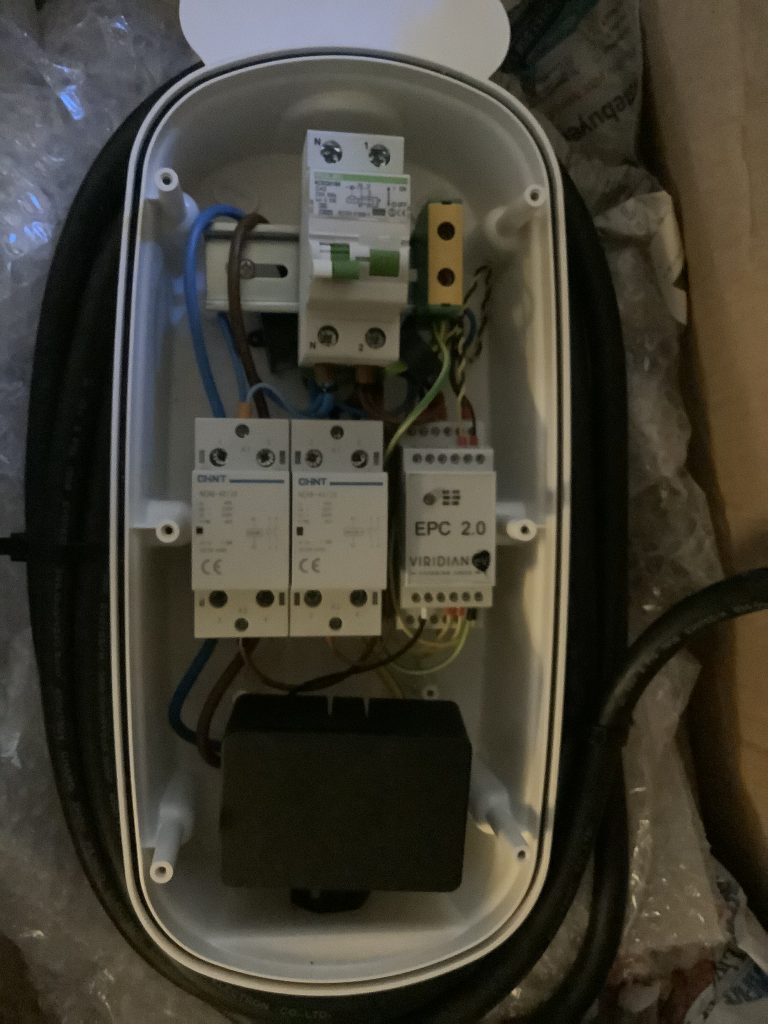
Stepped Mode 3 EVSE in consumer unit case
Most people of course will be content with an off-the-shelf charger, but I had some fairly uniquely requirements. One of the requirements that influenced my original charger was solar self-consumption (the charger automatically turns on when the home is in sufficient solar surplus) but this is now available commercially. My existing charger also adjusts its charge times around the Agile electricity tariff but this too is now available commercially with Ohme. However I still want to be able to coordinate it all centrally via my HEMS so that I can prioritise loads when constrained, or enable interactions like stopping the fixed battery discharging into the car at night and that’s not available commercially.
My solution is similar, but different, to my old charger. Both are modified from existing production chargers as a relatively affordable source of parts, but the new one will retain the production case (because it needs to be waterproof for outdoor use) and be better protected electrically than the old one. It needs to be better protected as electrical standards have moved on and, being outdoors, it needs to be more sophisticated to make up for the UK’s somewhat unusual earthing system (at least by international standards). It will also be smarter, but that will be described in later posts.
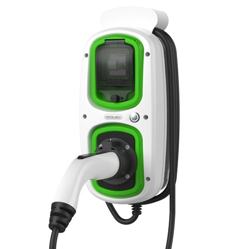
Commercial Mode 3 EVSE
Commercial Mode 3 EVSE – 2nd donor
Donors for first and second Smart EVSE.
The most common earthing system in the UK involves a cable between the home and the substation called a Protective Earth Neutral (PEN) conductor which, as its name implies, provides both the neutral and earth on a single core. Remember PEN as it will come up later..
My new charger will also be higher power than the old one. The old one is designed for 10 Amps continuous grid load (16 Amps peak from solar) based on the limitations of my garage supply, but the new one is designed for 32 Amps continuous load in anticipation of a future fully-electric vehicle. I have owned a fully electric vehicle previously, but for the moment both our vehicles will be plug-in hybrids. Some would argue the case for one being an Extended-Range Electric Vehicle (E-REV) or Range-EXtended Battery Electric Vehicle (REX BEV).
Similar production charger
My updated charger (work in progress)
Inside donor and modified EVSE.
The two internal pictures above show a similar production charger alongside my updated charger. The differences are (from top to bottom):
RCBO (combines over-current and residual current detection) – is actually carried over donor, but my charger came with a later model than the similar charger illustrated.
Earth terminal – I relocated from centre middle row to right top row to make space.
Residual Current Monitor (RCM) – The RCM (a small black box which encircles the live and neutral) sits behind the RCBO and triggers shutdown in the event of a D.C. fault.
PEN Loss Current Transformer – between the top and middle rails a small black ring sits around the earth cable. This is similar in principle to the RCM but rather than detect a D.C. fault on the supply, its role is to detect a fault current to earth. That’s not enough alone to provide PEN-loss detection alone but provides additional detection to that in the Protocol Controller (which we’ll get to soon).
Power contactor. The second rail starts on the left with a power contactor which disconnects the live and the neutral from the car when not charging. Mine is similar to the Rolec original, but smaller,
Switched Protective Earth (SPE) contactor. In the centre of the unit sits a second similar contactor, only this one switches the earth. Switching an earth is unusual but is required to protect against a failure of the PEN conductor between home and substation. The power contactor will not close and the car will not charge if the SPE is open with the result that the car is completely isolated from the mains supply during this failure mode.
Protocol controller. To the right of the centre rail is the protocol controller. This replaces the the original protocol controller which was in a similar position. The fundamental need to change was driven by the requirement to vary the charge current dynamically, but the new protocol controller also monitors not only the two current transformers (RCM and PEN-loss) but also the supply voltage in order to decide when to open the SPE contactor.
Raspberry Pi. At the bottom is an empty Raspberry Pi case to illustrate the sufficient space is available. The actual Raspberry Pi will be smaller. The role of the Pi is to tell the protocol controller how much current should be drawn. The Pi will tell the protocol controller via an analogue voltage, and the protocol controller will tell the car via a Pulse Width Modulated (PWM) signal – that is the width of a stream of voltage pulse indicates the current that the car should draw. The replaces the Programmable Logic Controller (PLC) and RF Solutions radio link in my older smart charger.
LED leads. At the very bottom 4 leads with red connectors leave the picture on the left which go to an external multicolour LED for charger status. I haven’t yet decided how to reproduce this. The donor LED is unsuitable as it only has three colours (Red, Green and Blue) but the protocol controller assumes that two further colours (white and purple) are also available,
Item
My original smart charger
New donor
My New smart charger
Switch
Double pole
+ RCBO
c/o from donor
RCM CT
No
No
New
PEN-loss CT
No
No
New
Power contactor
Yes
Yes
Yes
SPE contactor
No
No
Yes
Protocol controller
Viridian v1.0 (variable current)
Rolec (fixed current)
Viridian v2.0 (variable current with extra safety content)
Smart controller
Programmable Logic Controller (PLC)
No
Raspberry Pi
External communications
Radio (RF Solutions)
No
Wi-Fi (Part of Pi)
Status LED
LED on protocol controller visible through clear cover.
External LED. No LED on protocol controller.
External TBD. LED on protocol controller (not visible).
Comparison. between my existing smart charger, new donor, and new smart charger.
The new hardware will thus shutdown in the event of the following faults:
Over-current
Residual current (live – neutral)
DC current *
Earth leakage current *
Over-voltage *
Under-voltage *
Inferred PEN loss *
Lack of earth continuity between vehicle and wallbox
* These are additional protections in my new hardware that weren’t present in the old one.
At this point I should have a working dumb charger with 32 Amp capability, albeit that it’s untested as yet through lack of a compatible vehicle with a Type 2 vehicle inlet.
There are two items for which I’m awaiting delivery. Firstly I’ll be using a Raspberry Pi Zero to generate the current demand signal which will replace the empty black case in the picture and secondly I have a small 5V power supply on order to power that Pi.
Future posts will look at adding the smart controls.
It can’t be very often that an energy company blogs about its customers’ achievements. Last week it happened. Octopus Energy wrote a blog entitled “How to hack your home for cheaper, greener, energy with our open API” which featured the achievements of its customers, and Greening Me got two honourable mentions.
For those not familiar with geek-speak, API is Application Programming Interface which is a mechanism by which an app, webpage or computer program may give commands to, or receive data from, another program – often a web server. Such APIs are often closed (that is that they are only available for use by the creator’s own app or webpage etc), but in this case the Octopus APIs are open so that they can be used by others (including me) to create our own apps, webpages, or other integrations to get data from Octopus. That data may be future price information for a UK electricity region or the actual consumption from a specified electricity meter for example. Octopus document their APIs and encourage others to find innovative uses for them.
Other APIs that I use were either documented privately by the manufacturers of the equipment concerned, although the manufacturer has not put the API in the public domain, or were reverse-engineered by myself or others by looking at how the manufacturer used it or at the internet traffic that it generated and working out how we could use it ourselves for a slightly different purpose. Such purposes would include controlling equipment other than by the manufacturer’s own app, or collecting data into some non-supported form.
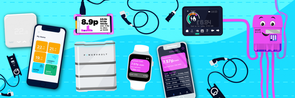
Diversity in third party solutions using the Octopus API.
Greening Me’s first mention in the blog came under the Smart Electric Vehicle (EV) Charging section where Octopus wrote..
One of our own smart energy pioneers, Greening Me, has used a Raspberry Pi and an add-on circuit board with our API to switch his electric car charger on/off and set the best time for his hot water immersion heater to run. He also has solar generation and so he can direct his solar power to either his smart car charger or hot water.
The first reference
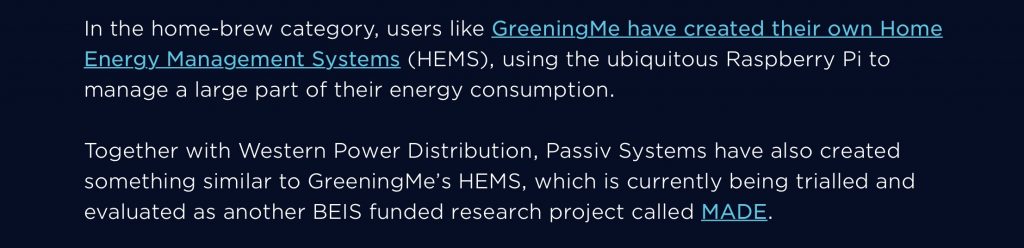
Later in the “I’ll do it myself (tech level 🌶🌶🌶)” section after describing a group of “smart home pioneers” Octopus wrote..
Together with Western Power Distribution, Passiv Systems have also created something similar to Greening Me’s HEMS, which is currently being trialled and evaluated as another BEIS funded research project called MADE.
The second reference
So it’s official – I’m a “smart energy pioneer” and a “smart home pioneer”. I also quite like the idea of being a “home hacker” in the positive sense of someone who makes their own home conform to their wishes. If you’d like to read the full blog post from Octopus Energy then you can do so here https://octopus.energy/blog/agile-smart-home-diy/.
Discussion elsewhere prompted me to look into what I spent on what you might term my energy smart systems relating to electricity consumption, so I thought I’d document it here.
Item
Description
Cost
Comment
1
Solar photovoltaic system (4kW)
£5,500
Bundled with ImmerSUN.
2
Powervault battery storage (4kWh)
£2,000
Free installation as part of UKPN trial.
3
ImmerSUN management system with monitoring.
£600
Estimate based on today’s pricing.
4
Remote-controlled car charger.
£300
Modified used charger from eBay. My own software.
5
Raspberry Pi items to make HEMS
£200
My own software.
6
Wet goods automation (WIFIPLUG x 2)
£70
TOTAL
£8,670
Prior analysis of items #1-#4 in pre-Agile days has suggested a total of 9 years to achieve payback on this investment through use of around 85% of the generated energy. Solar panels are potentially good for over 20 years operation, although I doubt the lead-acid batteries will still be operating for anything like that long.
The combination of item #5 with my Octopus Agile dynamic smart electricity tariff has resulted in my average bought electricity price being 7.75 p/kWh in 2019, about half the UK average. I suppose that I could make the same judgements and program items manually each day, but the HEMS significantly reduces my time commitment to achieve that.
Item #6 is my most recent addition. The sophistication of the algorithm combining the Agile tariff with a simple model of the cycle of each device is such that I would never achieve such a high quality result manually. However the saving is perhaps only a three pence each day so maybe £10 per year on my Agile tariff and thus 7 years to pay for the two smart plugs.
Much of this content is thus around 7 years to payback. The HEMS is potentially much quicker, but relies on having smart systems to control such as battery storage and car charger.
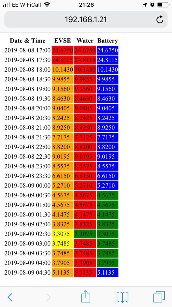
Yesterday provided a good example of my HEMS in action as the electricity price dropped quite low due to stormy weather conditions. Normally at this time of year the HEMS isn’t doing much with the storage battery as daytime solar output is enough to fully charge the battery, but yesterday low pricing was enough to automatically enable both battery charging and water heating overnight. Car charging was due to run anyway driven by the demand for an hour of charging, but battery charging and water heating was triggered by the low price rather than a needed to take power for a pre-defined period of time.
HEMS schedule 9th August
The screenshot above from my phone shows the HEMS’ plan for the the early hours of the 9th. The first price column shows one hour of car charging at the cheapest price. The second column shows half an hour of water heating as the electricity price has fallen below 3.5 p/kWh when it is assumed to be cheaper than gas. The third column shows four hours of battery charging when the electricity price is below 5 p/kWh.
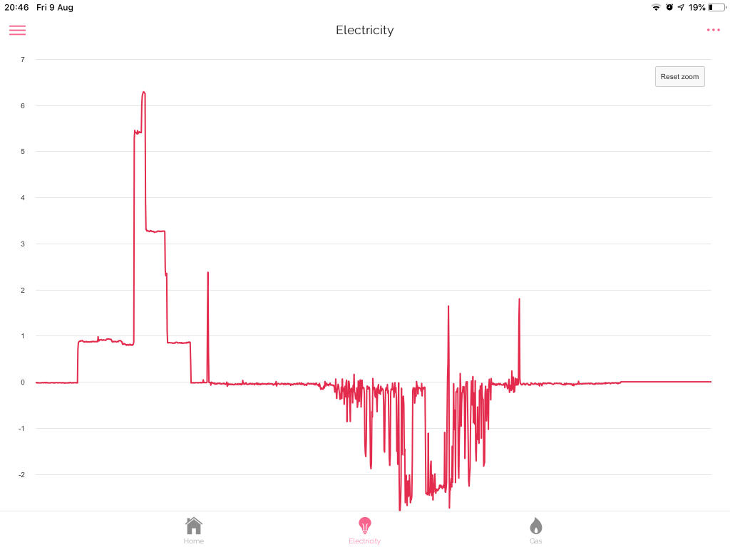
Metered electricity consumption (HAN side) 9th August
The above image from the HAN side of my smart meter shows the energy consumption of the house varying through the night in response to these requests from the HEMS – battery charging at the widest point, car charging above that for an hour, and water heating above that for 30 minutes.
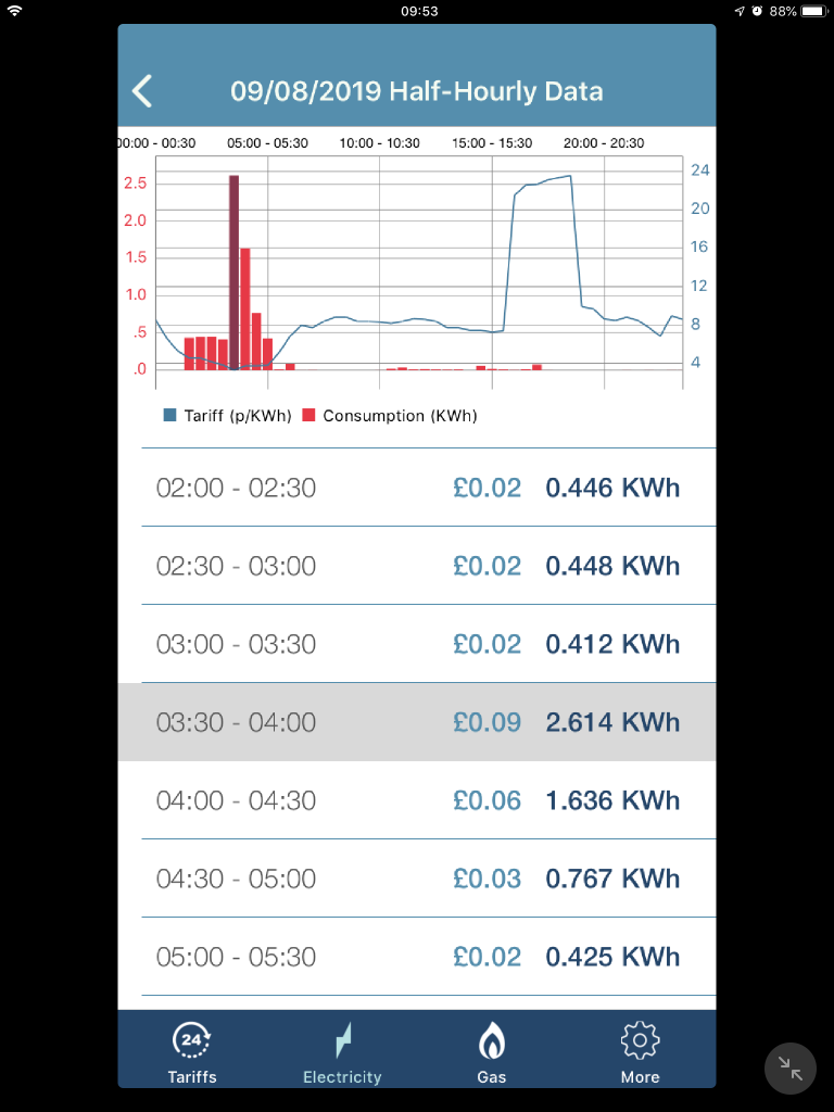
Half-hourly metered consumption (WAN side) and electricity price for 9th August
Finally this image shows the energy consumption versus price data for the same period shows how the action of the HEMS increases electricity demand as the price drops. Indeed on this day there was virtually no consumption at any other time.
For August 9th as a whole I paid 52 pence for 7.547 kWh of electricity. Taking off the 21 pence for the standing charge leaves 31 pence for the electricity kWhs alone, an average of 4.11 p/kWh.
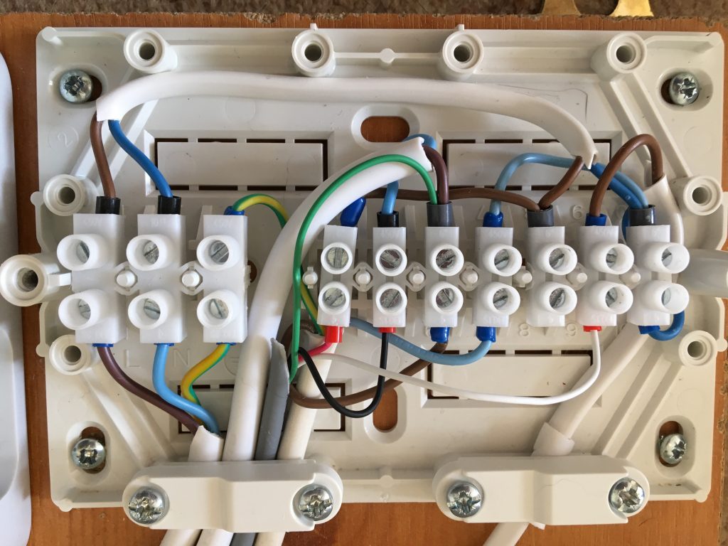
Today I’ve further refined the wiring of the relays on the HEMS. At the time that I’d originally wired it I didn’t have small enough flex, or indeed multi core, which created an unnecessary number of cables (one per used relay) of over large size (and thus difficult to insert into the terminals). During the week I acquired some smaller gauge multi core allowing me to wire all three relays with a single cable containing one live feed and three switched live returns.
Revised HEMS wiring with multi core to HEMS relay outputs
Of the 5 incoming / outgoing cables at the bottom (left to right):
Incoming mains (live / neutral / earth) from mains plug
Live and switched live to / from ImmerSUN output relay to activate car charger.
Live and switched lives to / from HEMS to activate car charger and water heating.
Red – live to contacts
Green – switched live for car charger direct – charge in response to price
Black – switched live for car charger indirect via ImmerSUN relay output – enable proportional charge in response to surplus PV
White – switched live for water heating – heat in response to price
Outgoing mains (switched live / neutral / earth) to RF solutions radio transmitter to activate car charger, and on the second cable clamp..
Outgoing switched live and neutral to ImmerSUN Boost relay input to enable immersion heater.
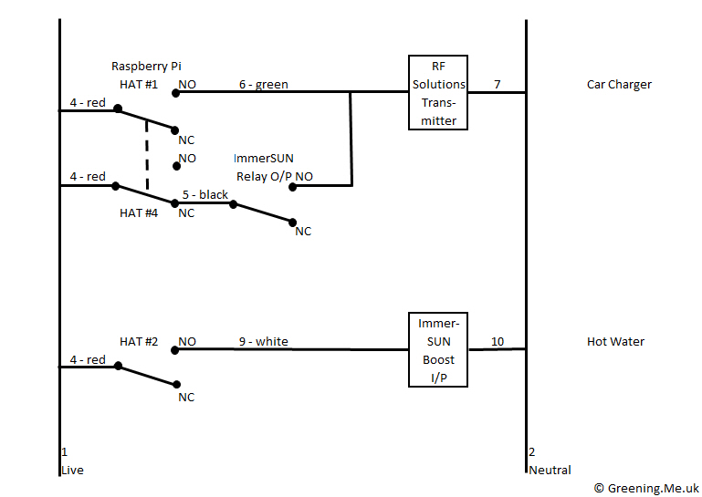
The revised wiring diagram looks like this..
Revised HEMS wiring #2
All of this still leaves one unused relay on the HEMS (HAT #3) and one unused proportional output on the ImmerSUN (#2; available for future expansion.
Initially even my smallest boot lace ferrules would not fit into the terminals on the HAT. Fortunately, once the ferrules has been crimped around the new cables, and flattened by squeezing in pliers, then the ferrules could be persuaded into the terminals.
After a series of quite detailed posts, I think that the time has come for an updated high level overview of what we have.
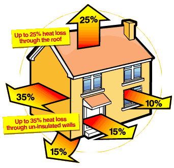
Heat loss from the home
We moved to our early 1970s house almost 4 years ago bringing with us our electric vehicle. The house had already been refurbished with new double-glazed windows, had cavity insulation (although that wasn’t recorded on EPC so must have predated the prior owners), and a token level of loft insulation. The existing gas boiler was arthritic, couldn’t heat the whole house, but was quite good at heating the header tanks in the loft! We had gravity-fed gas hot water (i.e. no thermostat or pump on the cylinder) which was completely obsolete, the cylinder dated back to the building of the house and had no immersion heater (although we had the wiring for one). So what did we do?
Space heating:
Eve Thermo eTRV
We substantially increased the loft insulation to reduce heat loss.
We had a modern condensing gas boiler installed to improve efficiency.
We updated to smart controls using eTRVs to set both temperature set points and schedules at room level. I built a smart interface to the boiler so that heating can be enabled remotely. I programmed a series of rules into Apple Home allowing the smart thermostats to enable the boiler when any thermostat wants heat and disable it when no thermostat wants heat. Some rooms also have additional rules linking heating to open windows or movement sensors. All of this reduces heat losses by only heating rooms that are (or will be shortly be) in use.
Electricity supply:
Solar panels
We installed our own solar panels given 4 kWp generation. (I also own a small share of a solar farm although there’s no contract that I’m aware of between that farm and my home energy supplier)
I invested in an immerSUN to maximise self-use of our own solar by enabling loads when surplus solar is available.
We switched to a green electricity supplier so when we need to buy electricity it comes from renewable sources.
We bought a small storage battery 4 kWh to store some of our solar production for use later in the day. Subsequently I can also use it in winter to buy when the electricity price is relatively low to avoid buying when the price is relatively high.
We chose a dynamic smart tariff to buy electricity at the lowest price based on market prices established the day before. The prices change each half hour and are established in the late afternoon on the day before.
Water heating:
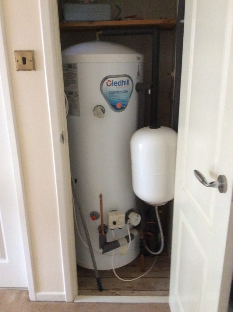
Hot water cylinder
We replaced the old hot water cylinder with a modern insulated one (to reduce heat loss) with a low immersion heater (to allow more of the water volume to be heated).
Our principal water heating is now by diverting surplus solar electricity proportionately to the immersion heater, that’s backed up by the gas boiler which is enabled briefly in the evening for water heating in case the water isn’t yet up to temperature, and when the electricity price falls below the gas price I can enable the immersion heater on full power.
All accessible hot water pipes are insulated.
Electric car charger:
Electric car charger.
I built my own electric car charger that takes an external radio signal to switch between four settings 0, 6, 10 and 16 Amps to help me adjust consumption to match to availability of output from my solar panels. (Subsequently such products were developed commercially with continuously variable current limits, but the limitations of my immersun and on/off radio signal don’t allow me to go quite that far. Having said that my car only does 0, 6, 10 and 14 Amps so I would gain no benefit from a continuously-variable charger paired with a 4-level car).
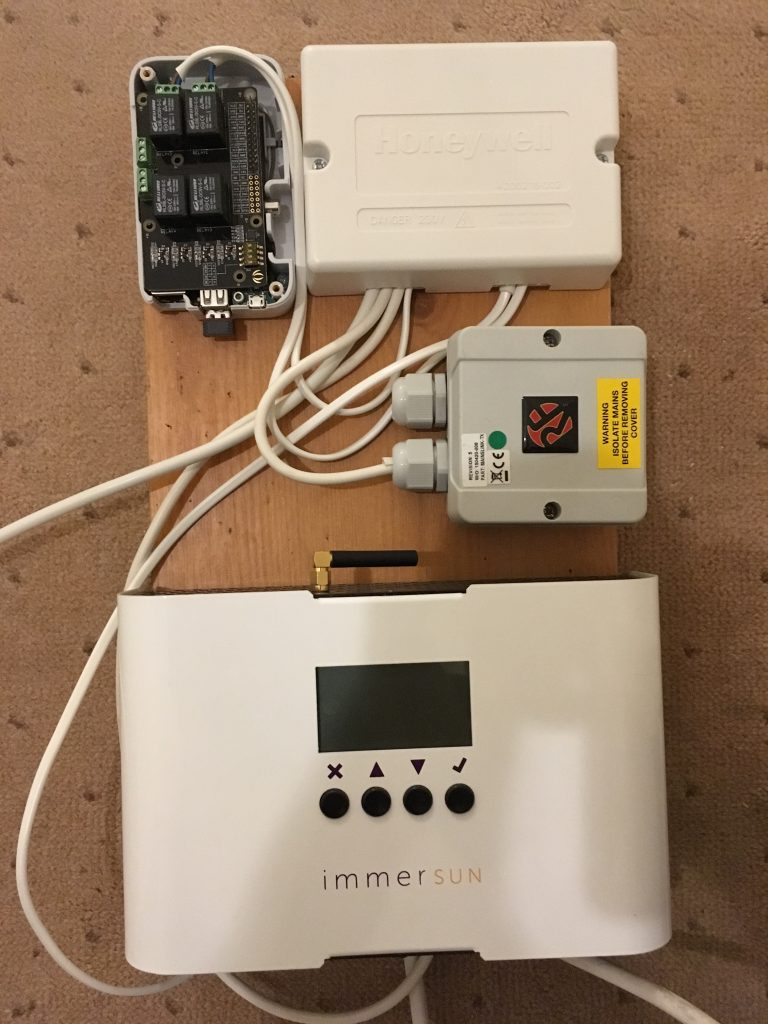
Smart electricity controls:
Smart controls top: HEMS (to manage bought electricity) and junction box mid: radio transmitter (to car charger) bottom: immersun (to manage self-consumption)
We have two systems for smart control of electricity:
The immersun to maximise self-use of our solar electricity by proportional control of loads.
A HEMS to manage the purchase of electricity (when necessary) at the lowest price by maximising consumption when the price is lowest.
When both systems want to enable loads (because the bought price is low and we have a surplus from our own panels) then cost is prioritised, so we’ll buy from the grid any demand not being met from our own panels.
Both systems are linked to 3 devices:
Battery storage. The immersun is configured to work alongside the battery storage with the battery storage as the top priority to receive surplus solar PV. The HEMS can switch the status of the battery as required to charge from the grid when the price is lowest, or to discharge when the price is highest, or indeed to revert to default behaviour.
Car charger. Second priority for the immersun after battery storage.
Immersion heater. Third priority for the immersun after car charging.
The future
I have no firm plans for the future. I’m toying with adding to the HEMS various features including:
Making the display switch between GMS and BST as appropriate (it’s all UTC at the moment).
Edit configuration via the web interface rather than a virtual terminal.
Control a domestic appliance. Our washing machine was replaced relatively recently, but the dishwasher is playing up a little and may be a candidate for HEMS integration where the optimum start time is selected to deliver lowest energy price.
Late last year I started adding the ability to optimise my electricity price by shifting some electrical loads around in response to a dynamic electricity tariff. My electricity price changes half-hour-by-half-hour and day-to-day, with the prices for the day ahead published each afternoon. I already had the ability to manage the same electrical loads to maximise use of the output of my own solar panels for some 3 years. The first load smartly controlled to follow my electricity costs was my electric car charging, but I have subsequently added optimisation of water heating and storage battery behaviour.
However, time has revealed an occasional issue arising when both the bought electricity price was low and a solar suplus was available, so both sources sought to enable the car charger; but in practice the vehicle didn’t charge. The issue here is that the car charger does a sanity check on the radio signal indicating that it should be operating, which fails since the combination of two signals driving a common radio transmitter can lead to excessive duration of the ‘on’ signal which fails the sanity check.
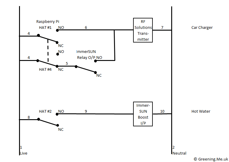
Revised HEMS wiring
My chosen solution is to disable one of the two signals sources when the other wants the car charger on. I’ve chosen to make the price signals via the HEMS the master, so when the HEMS wants to charge the car HAT #4 opens so that the ImmerSUN no-longer has influence over the car charger, and HAT #1 is used to control car charger behaviour. When the price is relatively high HAT #4 remains in the normally closed position and HAT #1 is open allowing the ImmerSUN to control charging behaviour via its output relay to use any surplus solar. (HAT refers to HArdware on Top – accessory circuit boards that mount on top of a Raspberry Pi. In my case board with 4 output delays. HAT #3 is currently unused.)
My current energy management arrangements are designed to maximise use of the output of my solar panels for lowest energy cost by diverting any excess to PowerVault storage system, car charger or immersion heater. I can also manually configure the PowerVault and ImmerSUN to minimise costs of bought energy from the grid (I get 7 hours of cheaper night time electricity) by setting time periods for charging.
However as I move to a smart meter and smart tariff then I’m looking to start automating the selection of when to draw power from the grid based on costs that change half-hour-to-half-hour and day-to-day. The hardware to achieve this is illustrated here. To the right is a Raspberry Pi – a small computer with a wide range of connectivity – and to the left is a module that sIts on top and has four relays able to switch mains loads, although at the moment I only anticipate needing 2 of them.
One of the relays will switch the boost input to the ImmerSUN to enable water heating, potentially when electricity is cheaper than gas, and a second relay will operate the transmitter that turns the car charger on alongside the ImmerSUN’s relay output during the cheapest available energy times.
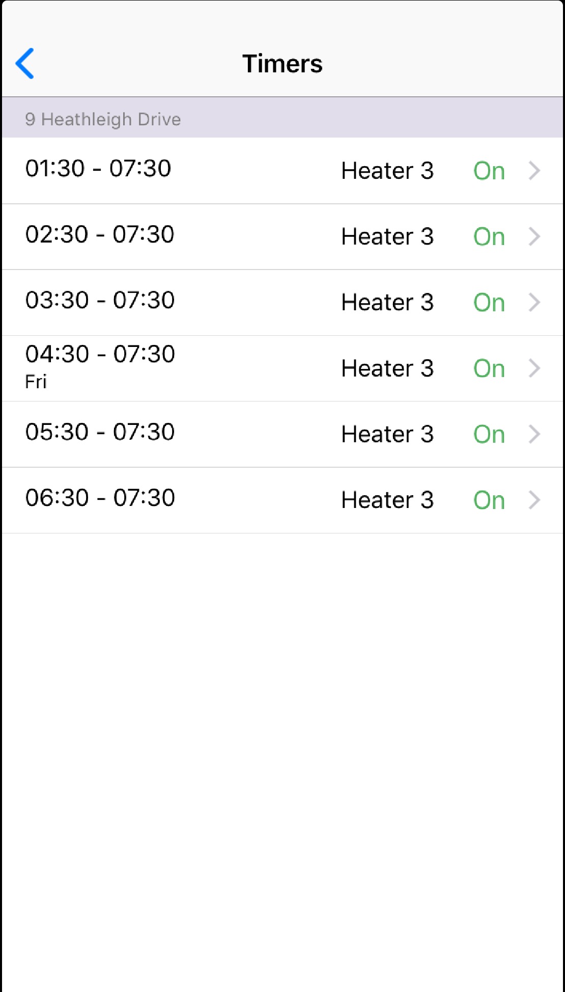
The image to the right shows the timers that can be used to enable the ImmerSUN outputs to draw power from the grid. I never use this for water heating as currently gas is always cheaper than bought electricity, but do use it to more or less effect seasonally to charge the car from cheap night rate power when there isn’t enough daytime solar. For the new HEMS I plan a table of 7 days specifying the number of hours required for each output and let the HEMS find the cheapest half hours to deliver the total hours required and enable the charger or water heating as required.