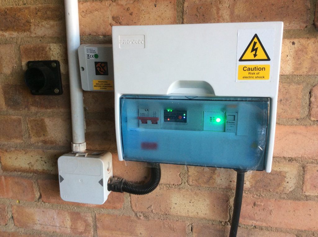
My electric car charger is built into a case more normally used for household consumer units. From left to right its contents are:
- 2 slots – Double pole on/off switch to isolate the incoming mains supply entering from below.
- 4 slots – Programmable Logic Controller (PLC) which takes 2 inputs (remote on/off via radio link and contactor status – see item #4) and generates 1 of 4 outputs (corresponding to off, 6 Amps, 10 Amps or 16 Amps). Beneath the PLC (and not visible inside the case) sits a circuit board with an array of resistors corresponding to the required current settings.
- 2 slots – Protocol controller which handles the Mode 3 handshake with the car and switches between current settings based on the selected resistor.
- 1 slot – Contactor which turns the power to the vehicle on/off based on the output from the protocol controller. Cable to car exits below.
- 1 slot – unused.
The dedicated charger circuit is fed from a RCBO in a small consumer unit on the other side of the garage which combines overcurrent protection (20 Amps) and Type A residual current detection (30 mA).
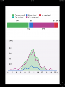
To the left of the car charger are two external items. On the far left is a cable dock into which the vehicle connector plugs when not charging the car to help keep the contacts clean. To the near left is a radio receiver which receives an on/off signal from a transmitter in the house. The transmitter is enabled when surplus solar power is available or when grid electricity is particularly cheap.


