Monthly Archives: December 2020

Charging onwards

I’ve recently had the opportunity through my day job to make a lot of use of an electric car that was not my own. However this presented the inconvenience that I couldn’t charge it on my own home wallbox in the garage since my wallbox has the older Type 1 5-pin connector to suit my own car, but the borrowed car has the more modern Type 2 7-pin connector. If you were buying a wallbox the obvious solution to charging vehicles of both types is a wallbox with a Type 2 socket, however I didn’t want to go down the new wallbox route as I wanted to retain my existing smart controls.

I couldn’t add a socket to my existing wallbox due to packaging constraints (where would I install the socket) and my unsuitable protocol controller (protocol controllers for socketed wallboxes are more complex as they need to decode cable current rating and operate a solenoid). Thus I decided to go down the two outlet cables route as the lowest cost solution given that I already had the cable. My outlay was limited to a relay to switch the power to the second cable, and a switch to decide which cable to use. Use of two relays ensures that only one outlet is live at a time, as there would be a risk of touching the exposed contacts of whichever cable was not in use.


Double Pole Double Throw (DPDT) switch with terminals.

The switch sits between the protocol controller and the relays. One side of the switch directs the relay output of the protocol controller to enable either the original relay for the Type 1 connector or the new relay for the Type 2 connector, while the second side of the switch connects the corresponding control pilot to the protocol controller. The control pilot handles the communication with the vehicle for things like current limits and handshakes.

Comparison of charger block diagrams

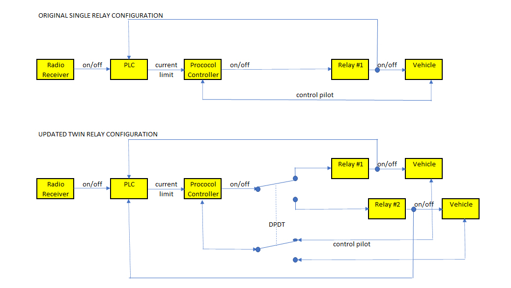
The open/closed status of each relay is also fed back to the Programmable Logic Controller (PLC) that sets the variable maximum current limit (off, 6, 10 or 16 Amps). The PLC had plenty of spare inputs for the connection to the new relay. Some small software changes were required so that the PLC respond to inputs from both relays (generally either relay #1 or relay #2 is on, or both relay #1 and relay #2 are off).
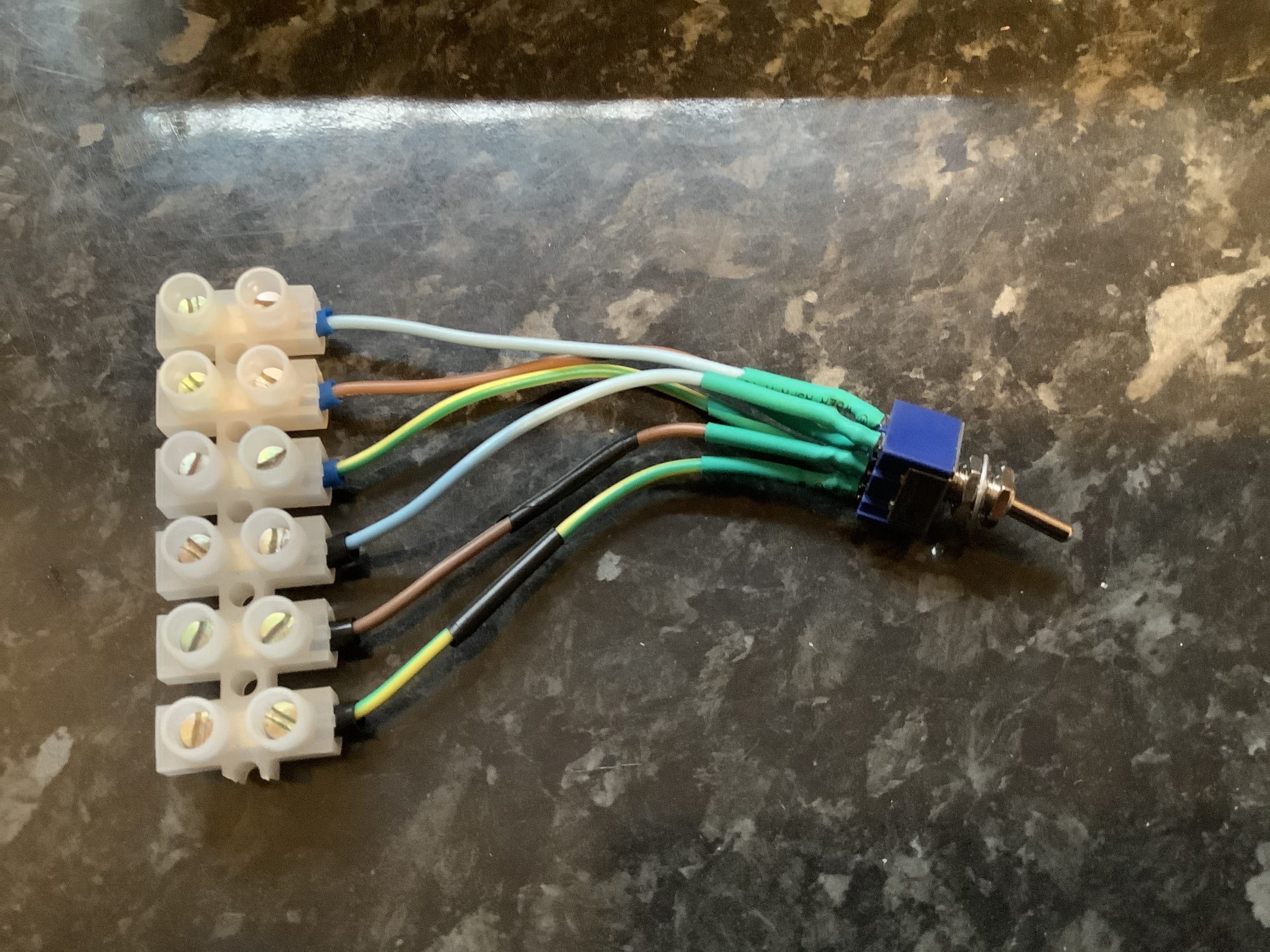
Updated wallbox with second relay to far right and second exit cable to right lower.

From left to right:

  • 2 slots – double pole isolation switch
  • 4 slots – Programmable Logic Controller (PLC)
  • 2 slots – protocol controller
  • 1 slot – original relay for Type 1 / J1772 connector and cable
  • 1 slot – new relay for Type 2 connector and cable
  • in side panel – DPDT switch

The resulting wallbox has demonstrated its capability to charge vehicles with either Type 1 or Type 2 inlets, responding to tariff-based on/off signals from my HEMS or surplus solar signals from my ImmerSUN.

Current clamps

Main electricity supply cutout with current clamp above

As previously noted, I recently had the main supply cut-out to my house uprated from 60 to 100 Amps in preparation for installation of an additional electric vehicle charger. That involved my Distribution Network Operator (DNO) replacing the fuse within the black fuse holder with the torn red label above and replacing the brown live and blue neutral cables between the cutout and the electricity meter to the top right of the picture. In my case the technicians involved automatically moved the black current clamp that sits above the cutout from the old live cable to the new one without even mentioning it, but it did occur to me that it would be worth documenting what current clamps I have, what they do and where they are for the benefit of any future trades who may not replace like-for-like.

I have two devices that currently use three current clamps between them:

  1. Immersun. Has two current clamps, one for control and one for solar generation data only.
    1. Immersun control clamp is around the main live feed between cutout and meter as pictured above and illustrated below. It measures any flow of electricity to the grid and prompts the Immersun to divert this to water heating or car charging.
    2. Immersun generation clamp is around the main live feed between the inverter for the solar panels and consumer unit and specifically inside the rotary isolator on this cable (being a good location where the live alone can be encircled without the neutral).
  2. Powervault battery. Has 1 current clamp inside the consumer unit which encircles both the incoming live and the live feed to the immersion heater. These two cables are orientated such that flow from the solar panels to the grid or to the immersion heater passes in the same direction through the clamp as illustrated below. (This is unorthodox and not what the installation manual describes, but is done to force the priority of the battery over the immersun when a solar surplus is available)
Positions of 2 of 3 current clamps.

There were previously three additional current clamps which were used by UK Power Networks (UKPN) my local DNO who part-funded my battery storage four years ago as part of a trial. Some of these clamps may still be present as I can still see some of the associated cables, but are no longer actively used as the associated data loggers are long gone. These clamps monitored: grid in/out (duplicates 1.1 above), battery in/out (duplicates battery’s own internal measurements), and solar panel in/out (duplicates 1.2 above).

DNOs tend to be concerned about excessive exports to local electricity grids which can cause voltage quality issues. Any export from a battery could add to any export from solar panels and could cause the DNOs preferred export limit to be exceeded. Given that the battery, as installed to the manufacturer’s advice, would measure the total export then it would be possible software within a battery to limit battery export such that the sum of battery plus solar export never exceeded the DNO’s recommended value. In practice the gross output of a 4 kWp solar array rarely exceeds the 16 Amp export limit even before the load of the home is subtracted to achieve the export from the home, so in many battery + solar installations there’s little prospect of the limit ever being exceeded even without such software limits.

The question that recently occurred to me is whether if a battery had such a software limit would that limit be defeated by my unorthodox installation of the battery’s current clamp?

Conceptual arrangement of clamps

My physical arrangement on the battery clamp encircling both the feed to the consumer unit and the cable to the immersion heater is equivalent to feeding the immersion heater from a connection between the meter and the consumer unit and having the clamp between that connection and the consumer unit. As such the battery clamp may read higher than the actual export since some of the power from the solar panels that is measured by the clamp may be diverted to the immersion heater without actually being exported. Thus, if the battery has a software function to limit to export, an arrangement like mine will cause the export limit to operate more aggressively than design intent and the DNO’s export recommendation will not be exceeded. Once the water is hot, and no further diversion occurs, then a battery clamp positioned like mine will record the same current as the meter and the Immersun’s clamp. Since I regard export as an error state then such a more aggressive limit on export is of no consequence to me.