
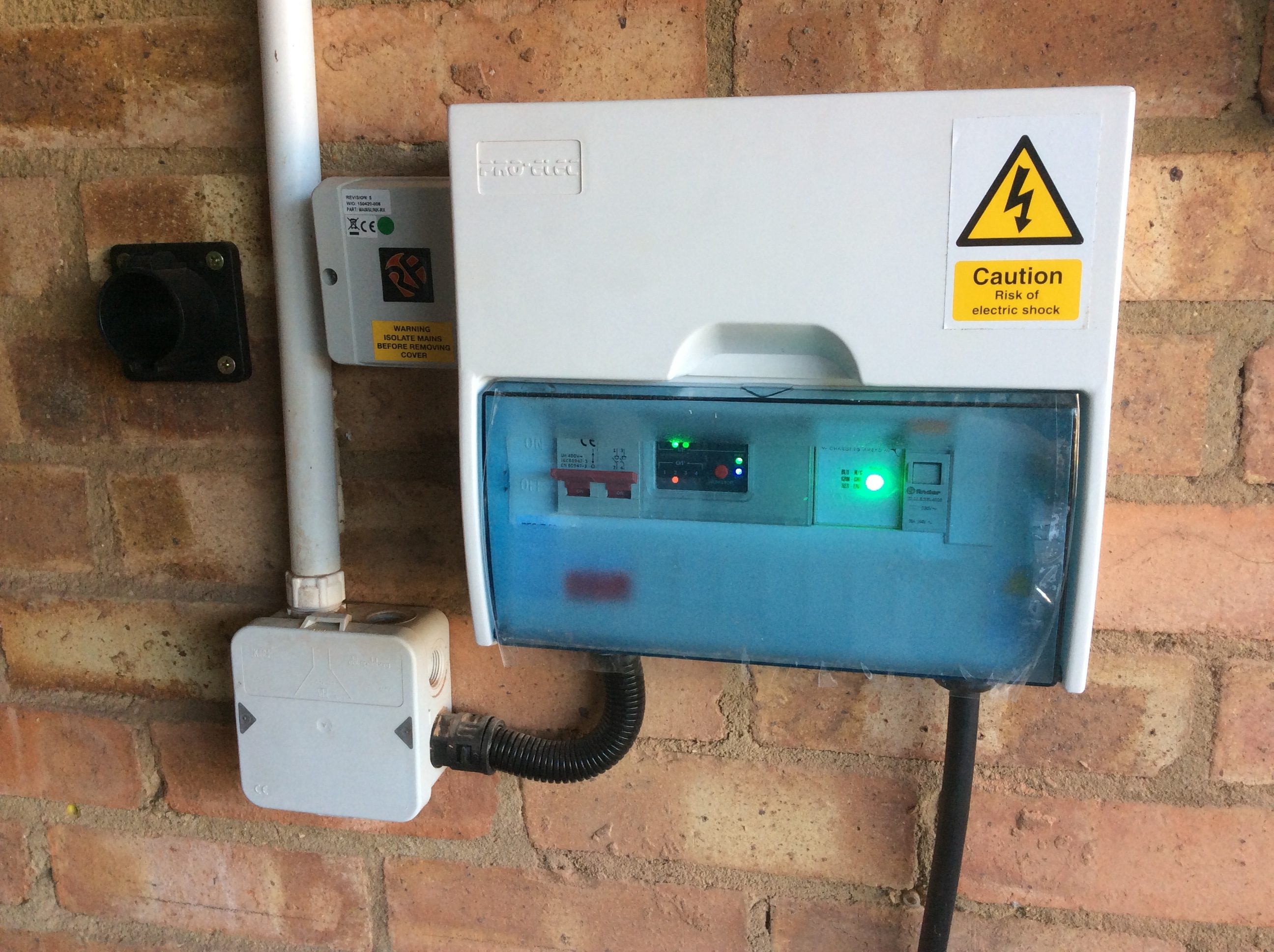
My electric car charger is built into a case more normally used for household consumer units. From left to right its contents are:
- 2 slots – Double pole on/off switch to isolate the incoming mains supply entering from below.
- 4 slots – Programmable Logic Controller (PLC) which takes 2 inputs (remote on/off via radio link and contactor status – see item #4) and generates 1 of 4 outputs (corresponding to off, 6 Amps, 10 Amps or 16 Amps). Beneath the PLC (and not visible inside the case) sits a circuit board with an array of resistors corresponding to the required current settings.
- 2 slots – Protocol controller which handles the Mode 3 handshake with the car and switches between current settings based on the selected resistor.
- 1 slot – Contactor which turns the power to the vehicle on/off based on the output from the protocol controller. Cable to car exits below.
- 1 slot – unused.
The dedicated charger circuit is fed from a RCBO in a small consumer unit on the other side of the garage which combines overcurrent protection (20 Amps) and Type A residual current detection (30 mA).
To the left of the car charger are two external items. On the far left is a cable dock into which the vehicle connector plugs when not charging the car to help keep the contacts clean. To the near left is a radio receiver which receives an on/off signal from a transmitter in the house. The transmitter is enabled when surplus solar power is available or when grid electricity is particularly cheap.
Please follow and like Greening Me:
Hello guy (I did find your name anywhere in the site, I am sorry) .
I am hit from your Charger Control Project, that seems good also for me.
I have a similar situation in my house in Italy: I have not battery storage but I have solar thermal plant so hot water is not a problem.
We have at home a couple of electric cars of which a Renault Zoe since 2013 and recently we also bought a Hyundai Ioniq Electric.
I am interested in realizing something like your solar driven controller to charge my car when I am at home.
I built a mode 3 EV charger using Mainpine protocol manager similar to yours. At the moment I use two resistors to change manually charging power from 8 Amps to 16 Amps.
So I ask you if you can explain details about PLC e radio link to ImmerSun device.
Thanks in advance and congratulations for your ability.
Best Regards from Pasquale
Hello Pasquale,
Thanks for following Greening Me.
My radio link consists of a transmitter / receiver pair called Mainslink from a company called RF solutions. They can be ordered here. Depending on the relative positions of your ImmerSUN-equivalent and car charger, you may be able to dispense with this and just run a cable between.
My PLC runs a ladder logic programme to choose between 0, 6, 10 and 16 Amps; but those values are just set by resistors as you describe and so the same programme could probably provide 0, 8 and 16 Amp settings. What’s the peak power output of your panels?
Of course a key component of my system is the ImmerSUN which generates the control signal when sufficient power is available. For you that threshold would be set to around 1,800 Watts (equivalent to 8 Amps) to either start charging at 8 Amps or switch up from 8 to 16 Amps. How do you plan to generate this signal?
I developed my charger a year ago, but if I were starting now I’d be considering a Zappi
Regards,