
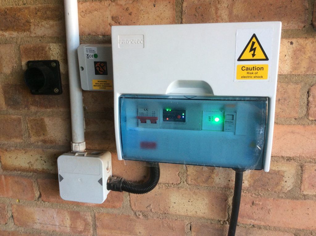
Well, it had to happen. After thirteen-and-a-half years of ownership of a plug-in vehicle we’re about to have two. I have had two briefly before during a vehicle changeover having bought a new one and then sold the old one privately, but now we’re replacing the hybrid that my wife generally drives with a plug-in hybrid. Not only will that give us two plug-in vehicles, but in the six years that I’ve owned the Ampera the standard inlet connector has changed from 5 pins to 7 pins so I can’t charge the new car on my existing smart charger either.
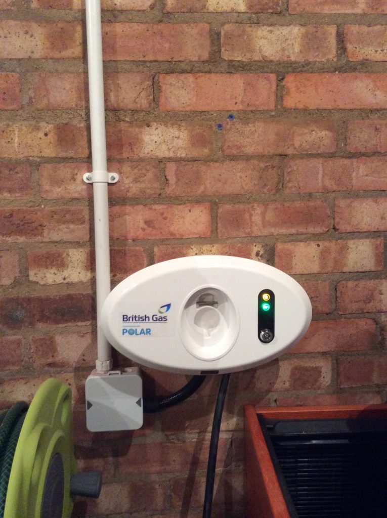
Most people of course will be content with an off-the-shelf charger, but I had some fairly uniquely requirements. One of the requirements that influenced my original charger was solar self-consumption (the charger automatically turns on when the home is in sufficient solar surplus) but this is now available commercially. My existing charger also adjusts its charge times around the Agile electricity tariff but this too is now available commercially with Ohme. However I still want to be able to coordinate it all centrally via my HEMS so that I can prioritise loads when constrained, or enable interactions like stopping the fixed battery discharging into the car at night and that’s not available commercially.
My solution is similar, but different, to my old charger. Both are modified from existing production chargers as a relatively affordable source of parts, but the new one will retain the production case (because it needs to be waterproof for outdoor use) and be better protected electrically than the old one. It needs to be better protected as electrical standards have moved on and, being outdoors, it needs to be more sophisticated to make up for the UK’s somewhat unusual earthing system (at least by international standards). It will also be smarter, but that will be described in later posts.
Commercial Mode 3 EVSE 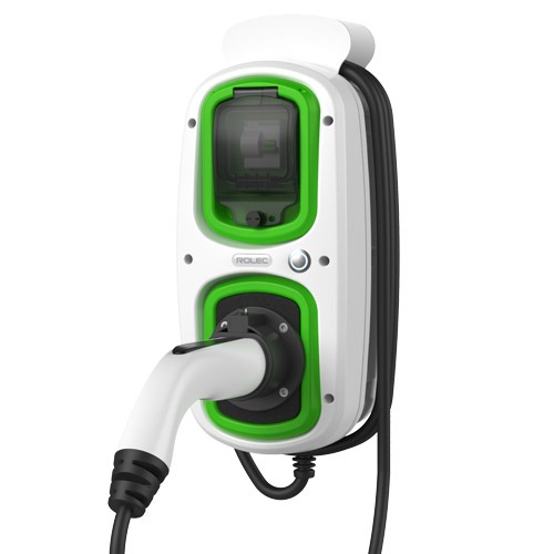
Commercial Mode 3 EVSE – 2nd donor
The most common earthing system in the UK involves a cable between the home and the substation called a Protective Earth Neutral (PEN) conductor which, as its name implies, provides both the neutral and earth on a single core. Remember PEN as it will come up later..
My new charger will also be higher power than the old one. The old one is designed for 10 Amps continuous grid load (16 Amps peak from solar) based on the limitations of my garage supply, but the new one is designed for 32 Amps continuous load in anticipation of a future fully-electric vehicle. I have owned a fully electric vehicle previously, but for the moment both our vehicles will be plug-in hybrids. Some would argue the case for one being an Extended-Range Electric Vehicle (E-REV) or Range-EXtended Battery Electric Vehicle (REX BEV).
Similar production charger 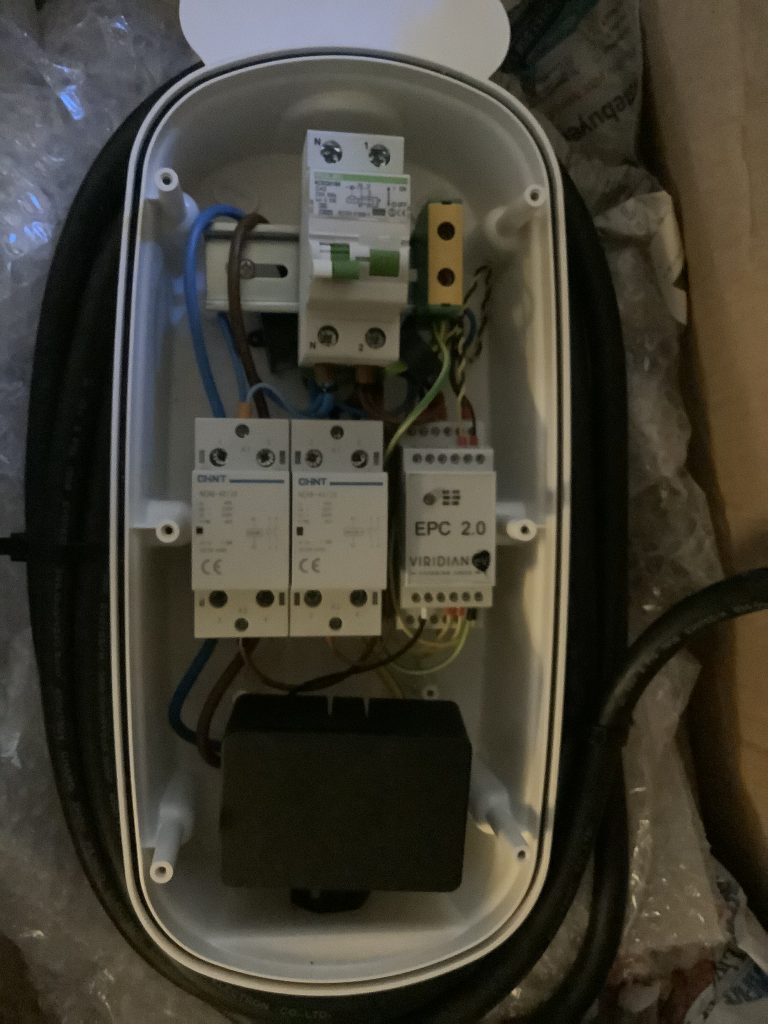
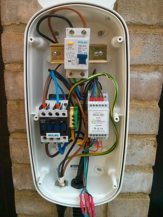
My updated charger (work in progress)
The two internal pictures above show a similar production charger alongside my updated charger. The differences are (from top to bottom):
- RCBO (combines over-current and residual current detection) – is actually carried over donor, but my charger came with a later model than the similar charger illustrated.
- Earth terminal – I relocated from centre middle row to right top row to make space.
- Residual Current Monitor (RCM) – The RCM (a small black box which encircles the live and neutral) sits behind the RCBO and triggers shutdown in the event of a D.C. fault.
- PEN Loss Current Transformer – between the top and middle rails a small black ring sits around the earth cable. This is similar in principle to the RCM but rather than detect a D.C. fault on the supply, its role is to detect a fault current to earth. That’s not enough alone to provide PEN-loss detection alone but provides additional detection to that in the Protocol Controller (which we’ll get to soon).
- Power contactor. The second rail starts on the left with a power contactor which disconnects the live and the neutral from the car when not charging. Mine is similar to the Rolec original, but smaller,
- Switched Protective Earth (SPE) contactor. In the centre of the unit sits a second similar contactor, only this one switches the earth. Switching an earth is unusual but is required to protect against a failure of the PEN conductor between home and substation. The power contactor will not close and the car will not charge if the SPE is open with the result that the car is completely isolated from the mains supply during this failure mode.
- Protocol controller. To the right of the centre rail is the protocol controller. This replaces the the original protocol controller which was in a similar position. The fundamental need to change was driven by the requirement to vary the charge current dynamically, but the new protocol controller also monitors not only the two current transformers (RCM and PEN-loss) but also the supply voltage in order to decide when to open the SPE contactor.
- Raspberry Pi. At the bottom is an empty Raspberry Pi case to illustrate the sufficient space is available. The actual Raspberry Pi will be smaller. The role of the Pi is to tell the protocol controller how much current should be drawn. The Pi will tell the protocol controller via an analogue voltage, and the protocol controller will tell the car via a Pulse Width Modulated (PWM) signal – that is the width of a stream of voltage pulse indicates the current that the car should draw. The replaces the Programmable Logic Controller (PLC) and RF Solutions radio link in my older smart charger.
- LED leads. At the very bottom 4 leads with red connectors leave the picture on the left which go to an external multicolour LED for charger status. I haven’t yet decided how to reproduce this. The donor LED is unsuitable as it only has three colours (Red, Green and Blue) but the protocol controller assumes that two further colours (white and purple) are also available,
| Item | My original smart charger | New donor | My New smart charger |
|---|---|---|---|
| Switch | Double pole | + RCBO | c/o from donor |
| RCM CT | No | No | New |
| PEN-loss CT | No | No | New |
| Power contactor | Yes | Yes | Yes |
| SPE contactor | No | No | Yes |
| Protocol controller | Viridian v1.0 (variable current) | Rolec (fixed current) | Viridian v2.0 (variable current with extra safety content) |
| Smart controller | Programmable Logic Controller (PLC) | No | Raspberry Pi |
| External communications | Radio (RF Solutions) | No | Wi-Fi (Part of Pi) |
| Status LED | LED on protocol controller visible through clear cover. | External LED. No LED on protocol controller. | External TBD. LED on protocol controller (not visible). |
The new hardware will thus shutdown in the event of the following faults:
- Over-current
- Residual current (live – neutral)
- DC current *
- Earth leakage current *
- Over-voltage *
- Under-voltage *
- Inferred PEN loss *
- Lack of earth continuity between vehicle and wallbox
* These are additional protections in my new hardware that weren’t present in the old one.
At this point I should have a working dumb charger with 32 Amp capability, albeit that it’s untested as yet through lack of a compatible vehicle with a Type 2 vehicle inlet.
There are two items for which I’m awaiting delivery. Firstly I’ll be using a Raspberry Pi Zero to generate the current demand signal which will replace the empty black case in the picture and secondly I have a small 5V power supply on order to power that Pi.
Future posts will look at adding the smart controls.