Regular readers will know that I’m into smart electricity tariffs as a means to save money and deliver a greener lower carbon electricity grid. In the last 12 months we’ve paid an average 7.2 p/kWh for electricity when we weren’t using our own from our solar panels. However you’ll never find these tariffs on price comparison sites who will happily ignore smart tariffs while earning commission by switching you to a standard flat rate or Economy 7 tariff that makes little difference to your costs versus what you may already have been paying. I’ve thus been pleased to support a project to develop a tool to help choose between these smart tariffs which are completely ignored by the existing switching services and price comparison sites and apps.
The project is now testing its solution.
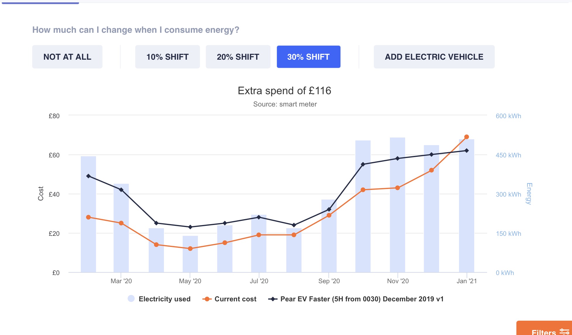
My usage and costs versus nearest rival tariff.
The system under final testing works in a completely different manner to the regular services. Rather than ask a few questions about consumption or costs, the new tool asks about smart meter details and then loads a year’s data indirectly from your smart meter. It thus knows precisely what electricity you consumed over the prior 12 months. The tool also asks about your flexibility to shift load to cheaper times in fairly simple percentage terms and then shows a range of tariffs (currently for testing real tariffs with false names) and their average monthly costs. You can overlay the costs of each alternative tariff in turn over your existing costs. You can see that, even with maximum flexibility, I’d have paid an extra £116 annually on the nearest tariff to my existing tariff.
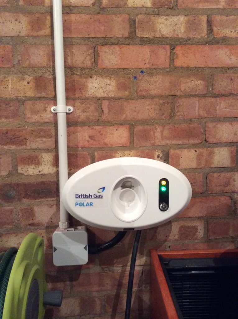
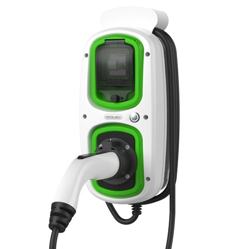
I’ve recently had the opportunity through my day job to make a lot of use of an electric car that was not my own. However this presented the inconvenience that I couldn’t charge it on my own home wallbox in the garage since my wallbox has the older Type 1 5-pin connector to suit my own car, but the borrowed car has the more modern Type 2 7-pin connector. If you were buying a wallbox the obvious solution to charging vehicles of both types is a wallbox with a Type 2 socket, however I didn’t want to go down the new wallbox route as I wanted to retain my existing smart controls.
I couldn’t add a socket to my existing wallbox due to packaging constraints (where would I install the socket) and my unsuitable protocol controller (protocol controllers for socketed wallboxes are more complex as they need to decode cable current rating and operate a solenoid). Thus I decided to go down the two outlet cables route as the lowest cost solution given that I already had the cable. My outlay was limited to a relay to switch the power to the second cable, and a switch to decide which cable to use. Use of two relays ensures that only one outlet is live at a time, as there would be a risk of touching the exposed contacts of whichever cable was not in use.
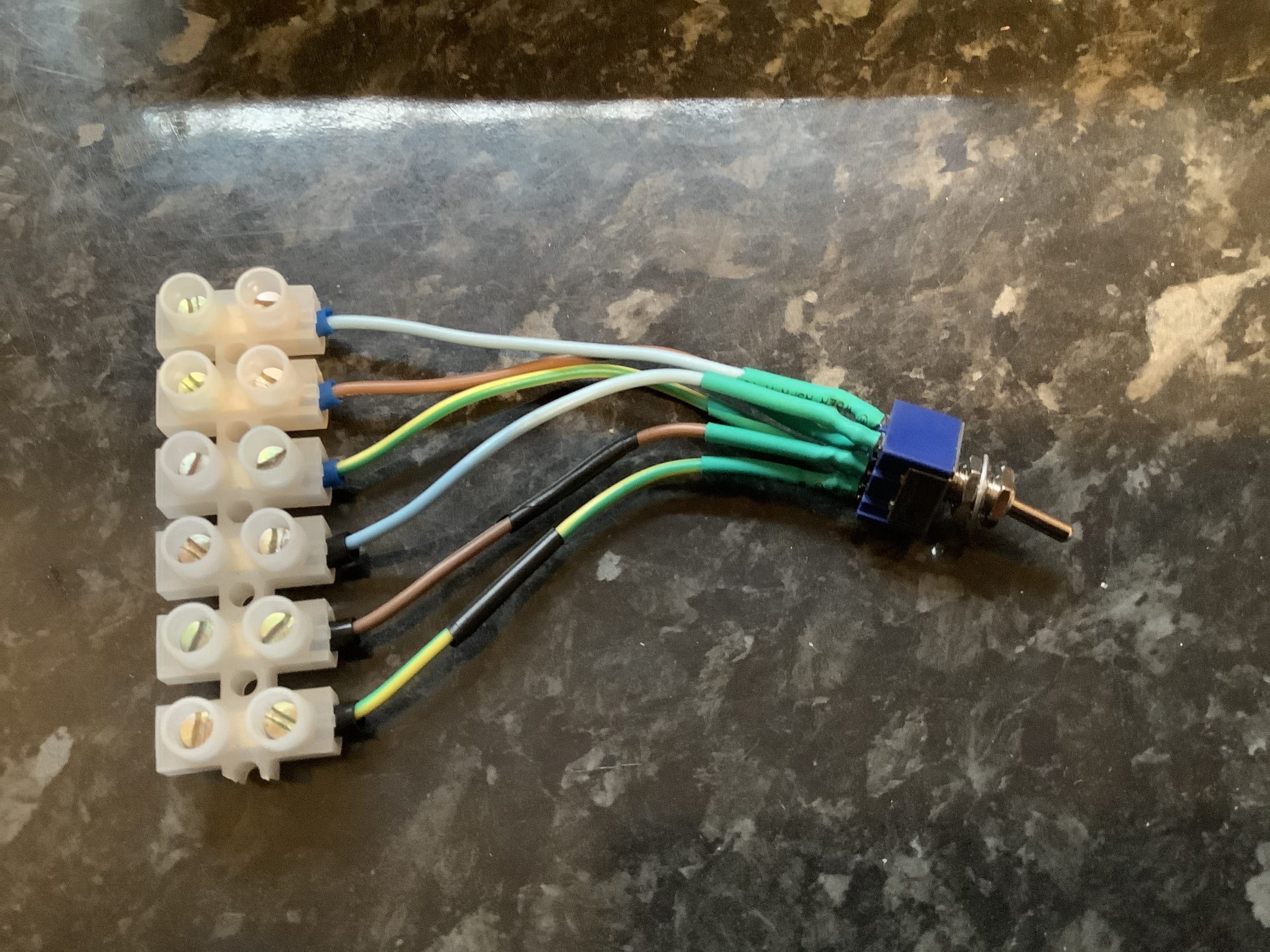
Double Pole Double Throw (DPDT) switch with terminals.
The switch sits between the protocol controller and the relays. One side of the switch directs the relay output of the protocol controller to enable either the original relay for the Type 1 connector or the new relay for the Type 2 connector, while the second side of the switch connects the corresponding control pilot to the protocol controller. The control pilot handles the communication with the vehicle for things like current limits and handshakes.
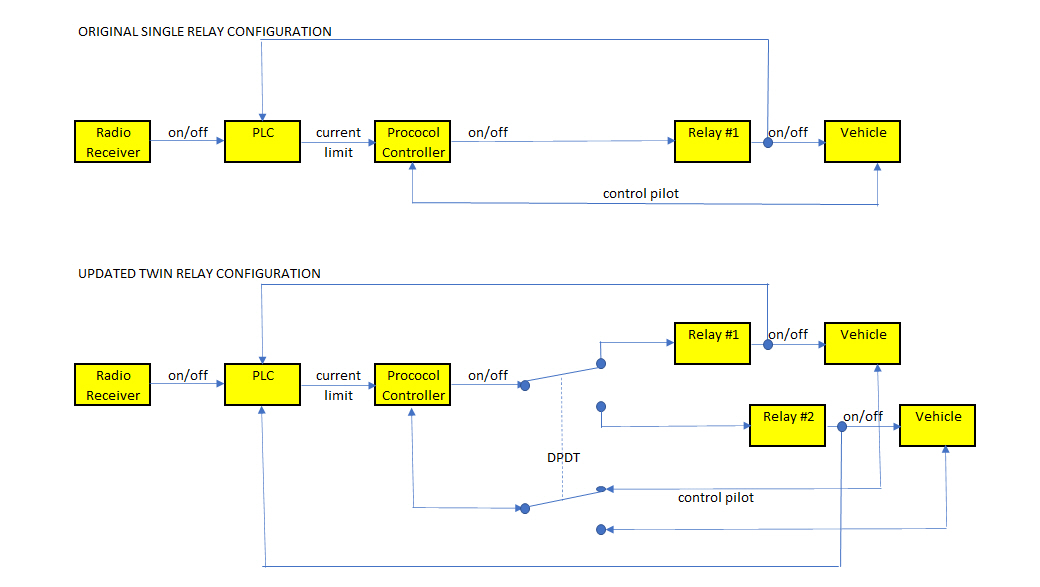
Comparison of charger block diagrams
The open/closed status of each relay is also fed back to the Programmable Logic Controller (PLC) that sets the variable maximum current limit (off, 6, 10 or 16 Amps). The PLC had plenty of spare inputs for the connection to the new relay. Some small software changes were required so that the PLC respond to inputs from both relays (generally either relay #1 or relay #2 is on, or both relay #1 and relay #2 are off).
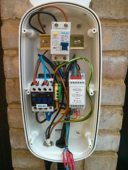
Updated wallbox with second relay to far right and second exit cable to right lower.
From left to right:
2 slots – double pole isolation switch
4 slots – Programmable Logic Controller (PLC)
2 slots – protocol controller
1 slot – original relay for Type 1 / J1772 connector and cable
1 slot – new relay for Type 2 connector and cable
in side panel – DPDT switch
The resulting wallbox has demonstrated its capability to charge vehicles with either Type 1 or Type 2 inlets, responding to tariff-based on/off signals from my HEMS or surplus solar signals from my ImmerSUN.
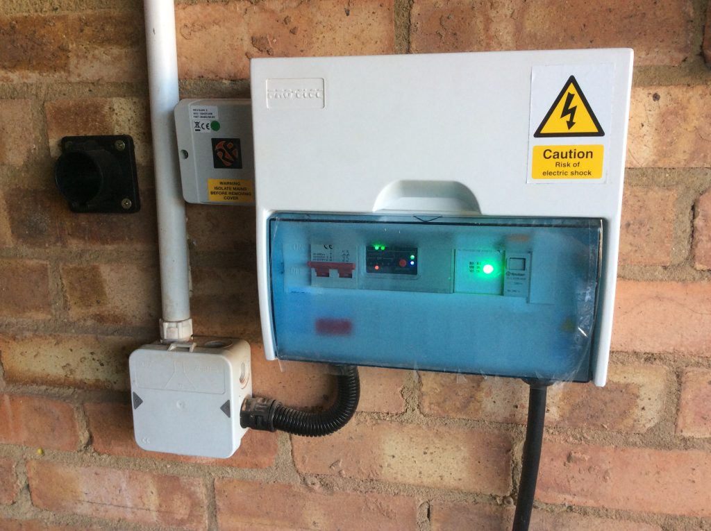
Main electricity supply cutout with current clamp above
As previously noted, I recently had the main supply cut-out to my house uprated from 60 to 100 Amps in preparation for installation of an additional electric vehicle charger. That involved my Distribution Network Operator (DNO) replacing the fuse within the black fuse holder with the torn red label above and replacing the brown live and blue neutral cables between the cutout and the electricity meter to the top right of the picture. In my case the technicians involved automatically moved the black current clamp that sits above the cutout from the old live cable to the new one without even mentioning it, but it did occur to me that it would be worth documenting what current clamps I have, what they do and where they are for the benefit of any future trades who may not replace like-for-like.
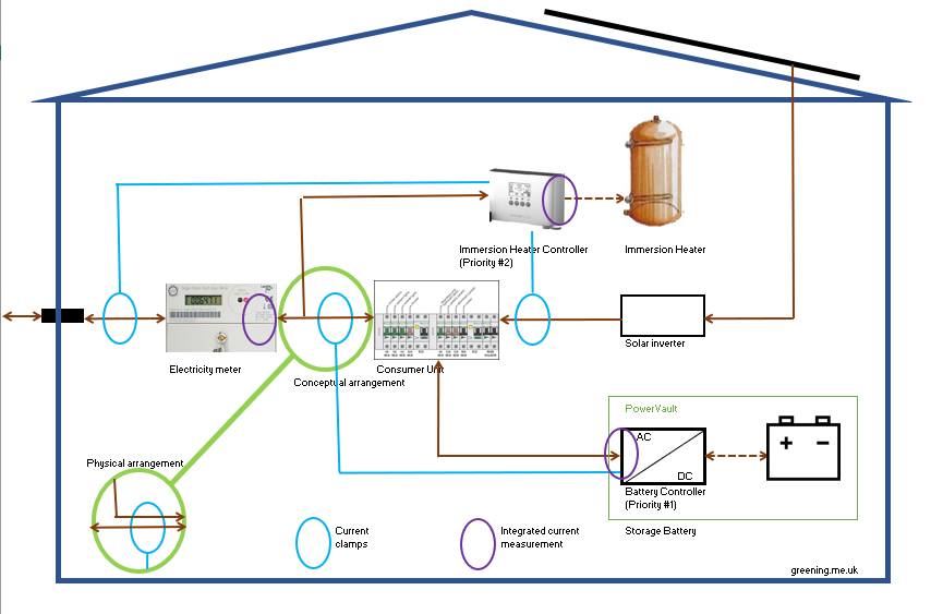
I have two devices that currently use three current clamps between them:
Immersun. Has two current clamps, one for control and one for solar generation data only.
Immersun control clamp is around the main live feed between cutout and meter as pictured above and illustrated below. It measures any flow of electricity to the grid and prompts the Immersun to divert this to water heating or car charging.
Immersun generation clamp is around the main live feed between the inverter for the solar panels and consumer unit and specifically inside the rotary isolator on this cable (being a good location where the live alone can be encircled without the neutral).
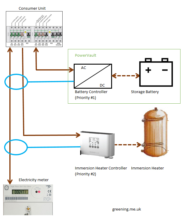
Powervault battery. Has 1 current clamp inside the consumer unit which encircles both the incoming live and the live feed to the immersion heater. These two cables are orientated such that flow from the solar panels to the grid or to the immersion heater passes in the same direction through the clamp as illustrated below. (This is unorthodox and not what the installation manual describes, but is done to force the priority of the battery over the immersun when a solar surplus is available)
Positions of 2 of 3 current clamps.
There were previously three additional current clamps which were used by UK Power Networks (UKPN) my local DNO who part-funded my battery storage four years ago as part of a trial. Some of these clamps may still be present as I can still see some of the associated cables, but are no longer actively used as the associated data loggers are long gone. These clamps monitored: grid in/out (duplicates 1.1 above), battery in/out (duplicates battery’s own internal measurements), and solar panel in/out (duplicates 1.2 above).
DNOs tend to be concerned about excessive exports to local electricity grids which can cause voltage quality issues. Any export from a battery could add to any export from solar panels and could cause the DNOs preferred export limit to be exceeded. Given that the battery, as installed to the manufacturer’s advice, would measure the total export then it would be possible software within a battery to limit battery export such that the sum of battery plus solar export never exceeded the DNO’s recommended value. In practice the gross output of a 4 kWp solar array rarely exceeds the 16 Amp export limit even before the load of the home is subtracted to achieve the export from the home, so in many battery + solar installations there’s little prospect of the limit ever being exceeded even without such software limits.
The question that recently occurred to me is whether if a battery had such a software limit would that limit be defeated by my unorthodox installation of the battery’s current clamp?
Conceptual arrangement of clamps
My physical arrangement on the battery clamp encircling both the feed to the consumer unit and the cable to the immersion heater is equivalent to feeding the immersion heater from a connection between the meter and the consumer unit and having the clamp between that connection and the consumer unit. As such the battery clamp may read higher than the actual export since some of the power from the solar panels that is measured by the clamp may be diverted to the immersion heater without actually being exported. Thus, if the battery has a software function to limit to export, an arrangement like mine will cause the export limit to operate more aggressively than design intent and the DNO’s export recommendation will not be exceeded. Once the water is hot, and no further diversion occurs, then a battery clamp positioned like mine will record the same current as the meter and the Immersun’s clamp. Since I regard export as an error state then such a more aggressive limit on export is of no consequence to me.
Two recent manufacturers’ announcements indicate that shortly the Apple HomekIt smart home ecosystem could be getting even more robust. The announcements concern threading which creates a mesh between smart home devices. Apple have announced that the HomePod mini smart speaker will be their first device with threading capability, while Eve have announced that an imminent software update will add this capability to both Eve Door and Window and Eve Energy devices (of which we have six in total now).
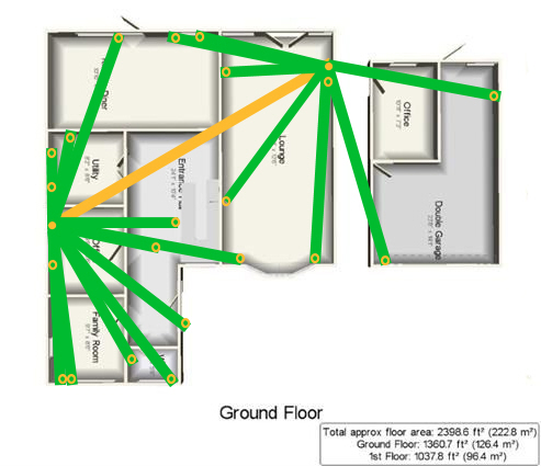
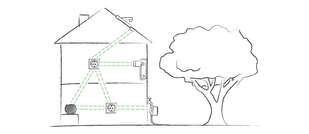
Pre-mesh
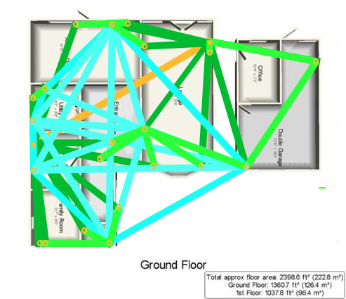
With mesh
The way the ecosystem currently works is that the hubs (of which we have two, both Apple TVs) communicate to each other via WiFi (or potentially wired Ethernet, both in orange) while my many smart home devices typically communicate with the nearest hub by Bluetooth (in dark green). This arrangement works well while both hubs are online, but if occasionally a hub is having issues then some devices are out-of-reach until the functionality of the hub is restored as Bluetooth struggles with the range.
However the new threading capability allows some Bluetooth devices to form a mesh (in cyan) where messages can can be passed by multiple routes from one thread-enabled smart home device to another and not just directly to and from hubs. Non-threading Bluetooth devices can then communicate to a nearby thread-enabled device (rather than a comparatively distant hub) and their messages have multiple alternative paths via the thread-enabled devices to eventually reach a hub.
BLE devices communicating to HomePod Mini hub via thread-enabled devices.
I had previously considered the Eve Extend as device capable of extending coverage to distant Bluetooth devices, but I see threading as much more attractive for me as follows:
Eve Extend is configured to relay signals from a predefined set of devices (which threading does not require pre-definition),
Eve Extend only covers some devices and in particular not my first-generation Eve Thermos (while threading supports any device, although only a limited range of devices form part of the mesh), and
Eve Extend device allocation is fixed (so if the Extend goes down the connection goes down) but threading is dynamic, so if a threaded device goes offline (such as due to a flat battery) then an alternative path may be found via other devices in the mesh.
Eve Extend does however work differently in that it sits between BLE devices and WiFi and could thus extended coverage over a greater distance since WiFi carries further than BLE.
As we look to install a second electric vehicle charger that becomes a challenge for the electrical supply to our home which is limited to 60 Amps. I recently saw a page online by which our DNO (District Network Operator) – UKPN – could be requested to install an uprated fuse.
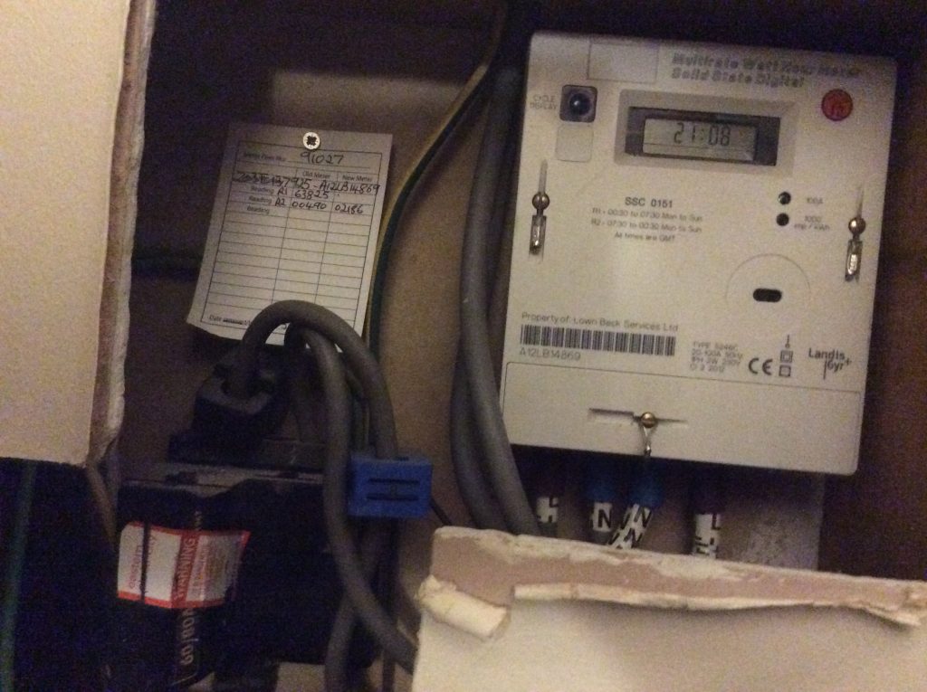
60 Amp cutout and Economy 7 meter
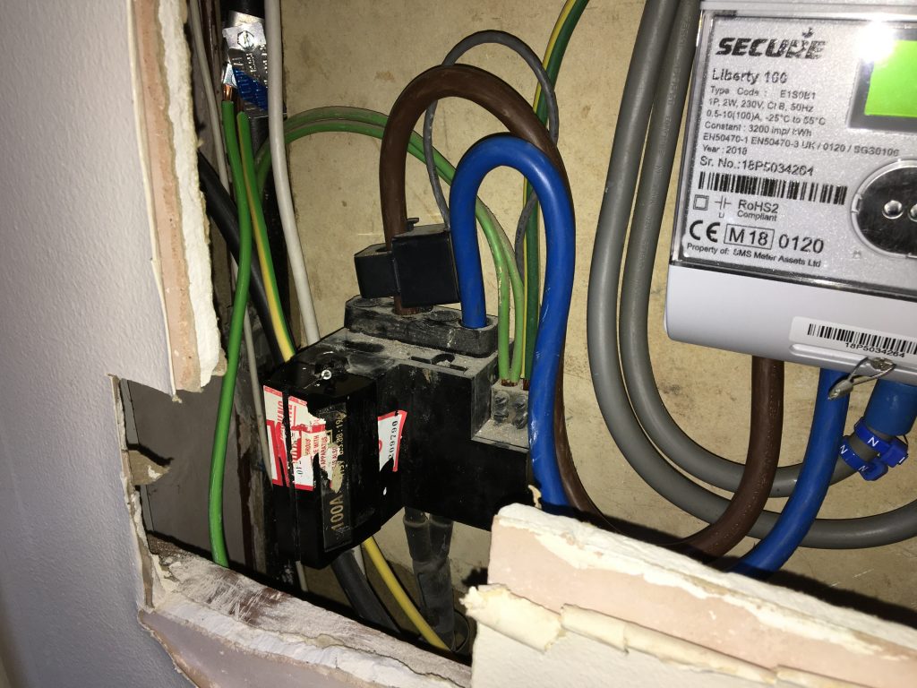
100 Amp cutout and Smart Meter
A comparison of cutouts and meters
(Some readers may be curious regarding the irregular size of the hole around the cutout and meter. When we looked around the house I recall reflecting upon the fact that I didn’t know where the meters and consumer unit were. The mystery was explained when we moved in and these items were found to be behind a false wall in what is now my study having previously been concealed by pictures. We continued the practice by buying pictures to conceal three holes in the wall (now four) covering: electricity meter, gas meter and consumer unit (adding generation meter and isolator for solar panels).)
I’m delighted to report how smoothly the change went. I was advised that it might be the case that the work could not proceed on a first visit, and that it might be necessary for my electricity supplier to update meter and/or cables from meter to consumer unit; but the installation proceeded on the first visit with not only the cutout changed from 60 to 100 Amps but also the cables between the cutout and the meter renewed. All of this at a price of precisely nothing.
I had been reasonably confident in the meter as that had been renewed almost exactly two years ago when we moved from Economy 7 to a smart tariff, but I was less clear about the cables between the meter and the consumer unit. In the event all was fine.
The extra 40 Amps should now mean that I have no issues adding a 7.4 kW car charger which draws 32 Amps. I have previously posted about the new car charger. My task of writing the software for it is now considerably simplified as I shouldn’t need to worry about managing the after diversity maximum demand of the house to not exceed 60 Amps, and can concentrate on the other smart controls – tracking my solar surplus and responding to the smart tariff.
We currently have eight Eve Thermo electronic thermostatic radiator valves (eTRVs) in service. These valves allow us to set heating schedules and target temperatures for rooms individually, for example don’t heat the lounge of weekdays before the evening or don’t heat the playroom after the children’s bedtime. All the existing valves are the original version.
However I’ve just bought two more valves with a view to expanding control to the bathroom and ensuite. I want to add these rooms as they tend to be rooms where the windows are left open (allowing heat to escape) and the ensuite in particular is often too hot and difficult to it’s difficult to regulate the temperature as it’s immediately above the boiler. These new valves are the second generation. So what are the differences between versions?
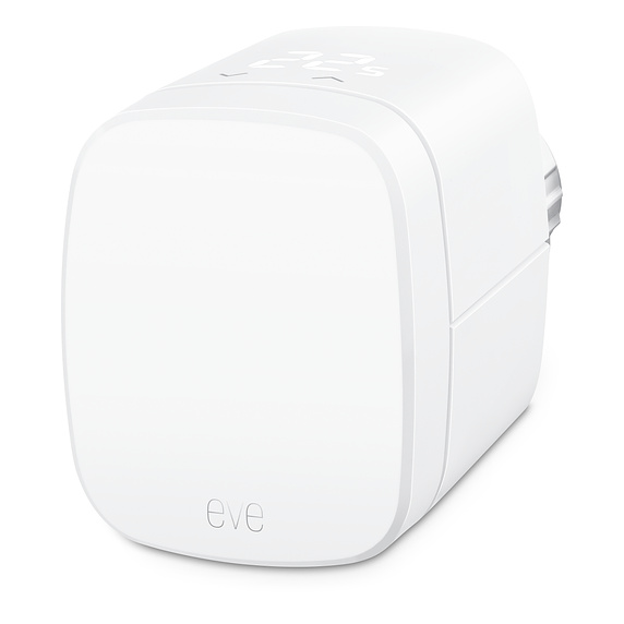
Eve Thermo eTRV
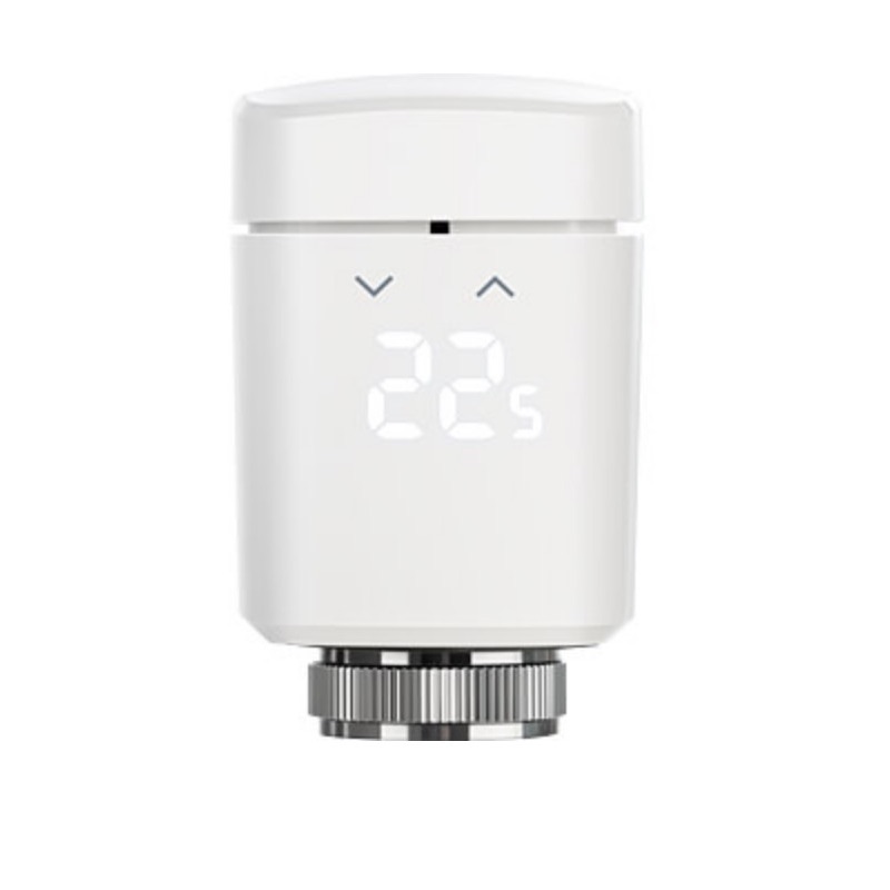
New Eve Thermo eTRV
Old and new Eve Thermos compared
The two versions are very similar if not the same size. The most obvious difference is that the new version has a small display and buttons allowing the temperature to be adjusted. A setup item allows the orientation of the display to be adjusted so that the temperature display is the preferred way up. The display illuminates briefly when the buttons are used to adjust the temperature.
However there are other small differences:
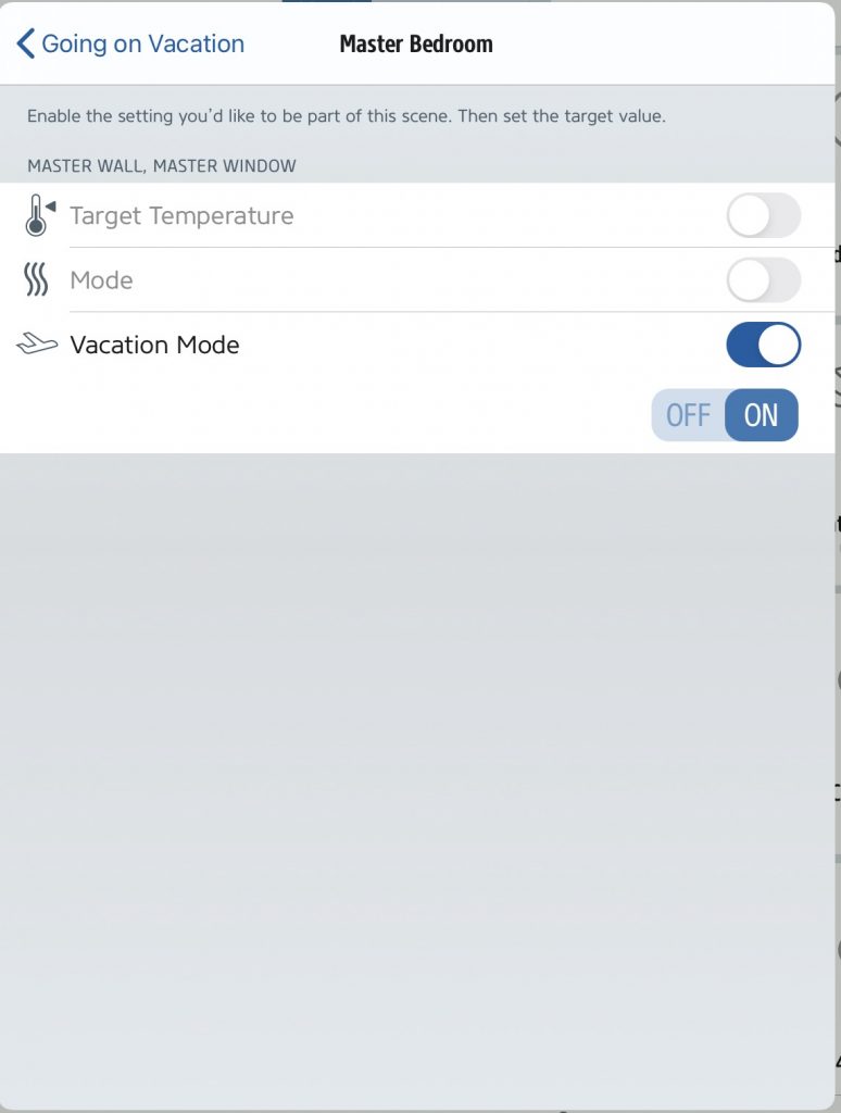
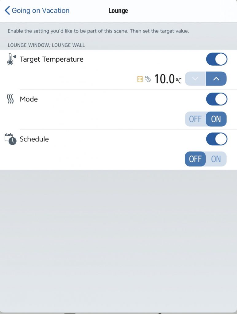
Vacation mode. The older version has a vacation mode for winter vacations when the schedule is disabled, but heating will be enabled below the lower temperature set point. The newer version doesn’t seem to have this mode, so my existing vacation scene sets these individually: mode = on, schedule = off, temperature = 10 Celsius to achieve the same result.
Lower temperature set point. In the older version the minimum possible scheduled temperature stored in a valve was 10 degrees, but a scene could set a lower temperature down to 5 degrees. I use this facility overnight to stop a rarely-used room pulling on the heating overnight in winter while still providing frost protection. However the newer version seems to have a common minimum temperature of 10 degrees. I have thus modified and renamed a scene that previously explicitly set 5 degrees to set minimum temperature, that is either 5 or 10 degrees according to valve generation.
Original version
Second version
I plan to install my two new valves in the lounge which has two radiators, and use the displaced older valves in the bathroom and ensuite.
After installation we’re now up to 10 eTRVs divided between 8 rooms (bathroom, cloakroom, daughter’s bedroom, ensuite, lounge x2, master bedroom x 2, playroom and wife’s study). Most of these rooms have individual schedules; while bathroom, cloakroom and ensuite heating is on when any other room heating is on. The latter also have window sensors and are disabled while the window is open, while the lounge also has a movement sensor which curtails heating in the evening if no movement is detected (which otherwise provides heating for my wife’s late film viewing).
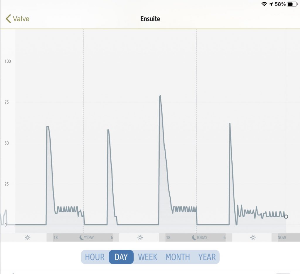
Valve position for the ensuite eTRV.
The image above shows the operation of the eTRV in the ensuite which was previously the room with the greatest difficulty in maintaining an appropriate temperature – often being too hot as almost directly above the boiler. Here we can see brief morning openings and much longer evening openings on weekdays, and heating all day on Saturday. In all cases the valve initially opens wide (60-80%) to warm the room up, and then gradually closes over time until the temperature is maintained with a relatively small opening (~10%).
The system has several modes:
Summer – which provides temperature monitoring, but no control.
Vacation – which provides minimum temperature control, but no schedules.
Winter – which provides temperature scheduling with two schedules available – one for working days and one for non-working days (not necessarily weekdays and weekends) selected from a standard Apple calendar.
Last night I was refining some of my HomeKit automations (rules) and it occurred to me that it might be an idea to capture some tips from the last few years.
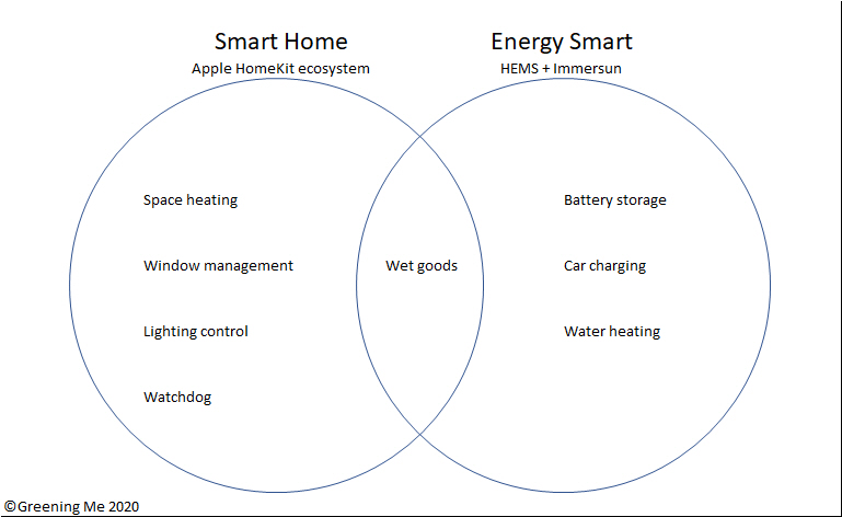
HomeKit versus HEMS functions
I currently have around 30 automations delivering:
Space heating – 8 eTRVs / smart valves linked to a smart plug for boiler control and both movement and window sensors.
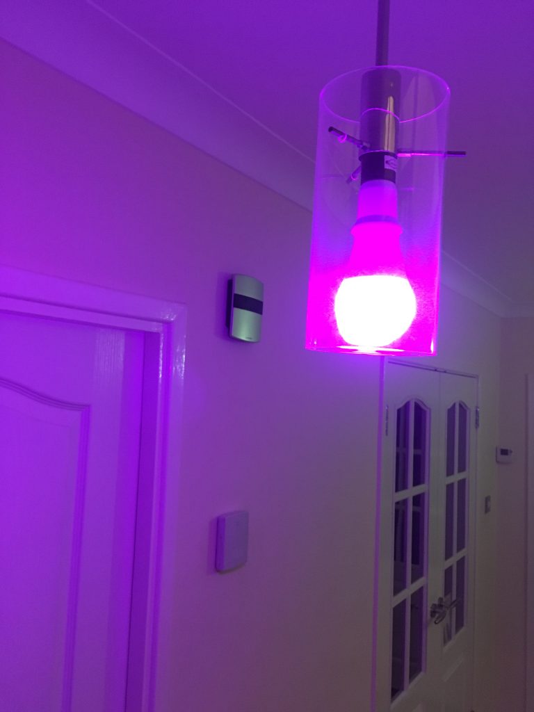
Window management – 4 window sensors and a movement sensor indicating via colours smart bulb when windows are left open (typically checked prior to leaving the house)
Lighting control – dusk-to-dawn lighting with colour-override by window management.
Watchdog – robustness aid.
Wet goods – control and dishwasher and washing machine in conjunction with HEMS.
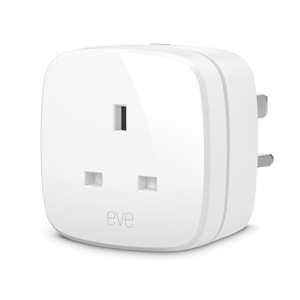
Eve Energy smart plug
Eve Thermo eTRV
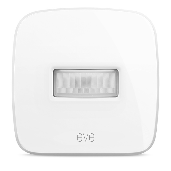
Eve Motion
Eve Door and Window
In total I currently have:
8 smart radiator valves (eTRVs)
6 smart plugs
4 door / window sensors
3 smart bulbs (two coloured + 1 on/off)
2 movement sensors
1 environment sensor (temperature, humidity, air quality)
So, what are my tips:
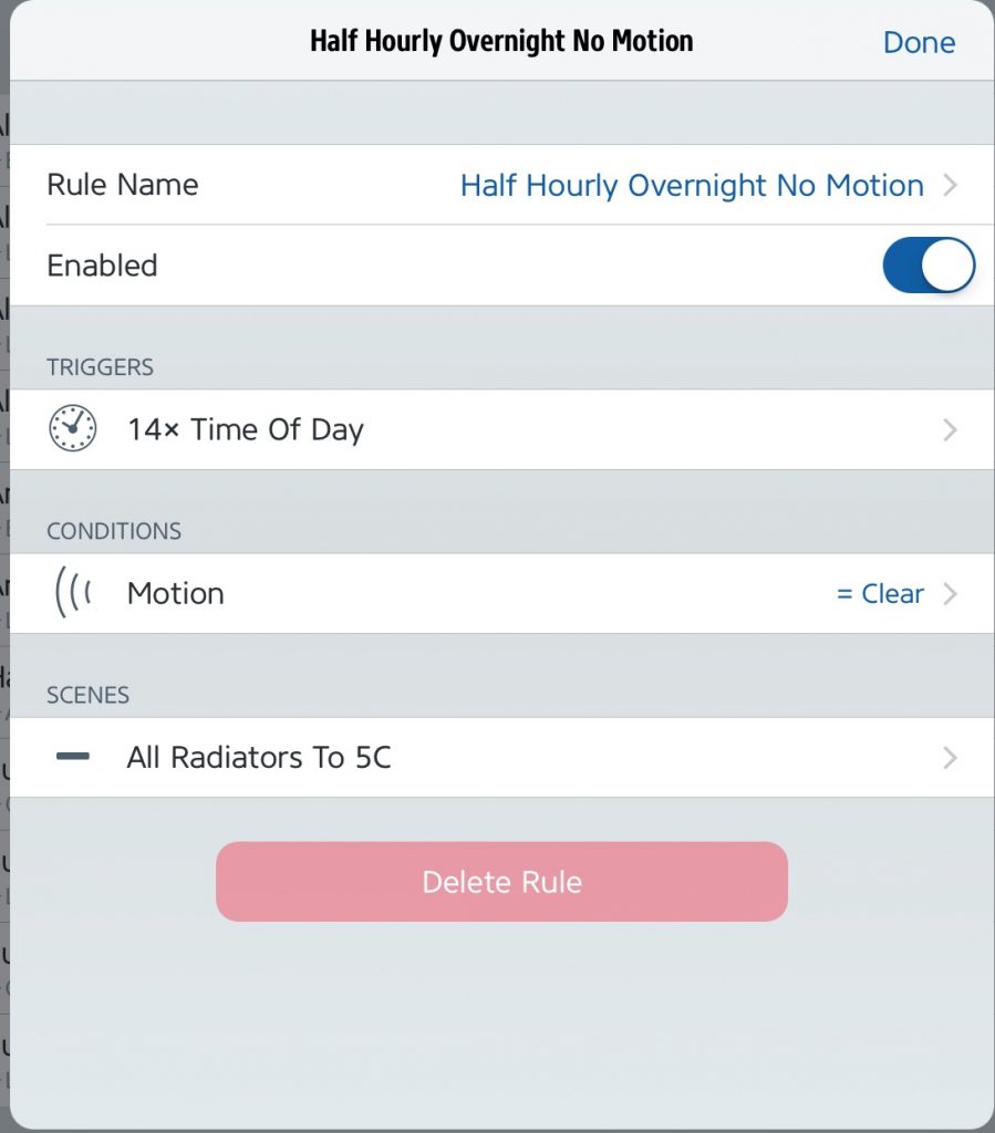
It Is much more intuitive to write rules in the Eve app.
The free Eve app can pretty much do everything that Apple’s own Home app can do for HomeKit devices (not just Eve’s own devices). The construction of rules in the form: IF {any of one of more triggers} AND {all of none or more conditions} THEN {set one of more scenes} is very intuitive in the Eve app.
Eve also allows rules to be names, whereas Apple’s own Home app sets names to a trigger condition, so if you have many rules as I do with common triggers then you end up with a confusing list of rules with duplicates names which need to be opened to tell one from another.
A rule in the Eve app.
Comparison with conventional logic. Simple IF rules are very straightforward: IF {any of one or more triggers} THEN {set one or more rules}, however AND rules take a bit more thought: IF {list of AND conditions} AND {same list of AND conditions} THEN {set one or more scenes}.
A watchdog makes execution more robust. HomeKit rules are triggered by changes of state such as going from open to closed or from movement to no movement, but if some some reason a trigger is missed you may have the wrong scene set for hours. My watchdog rechecks rules every 5 minutes as described here.
AND rules. AND rules may be converted to use the watchdog principle by simply adding an additional trigger to reference the change of state of the smart plug used for the watchdog: IF {original list of AND conditions + new smart plug trigger} AND {original list of AND conditions} THEN {set one or more scenes}.
Simple IF rules. IF rules with single triggers are easily converted. The same principle applies to AND rules: If {original single trigger + new smart plug trigger} AND {original single trigger} THEN {set one or more scenes}.
Complex IF rules. IF rules with multiple triggers are more involved to convert to the watchdog principle. If you just add the smart plug to the trigger list as per the earlier AND paragraph then the rule triggers every time the smart plug cycles. If you were to add the other triggers to the conditions list then the rule would become an AND not an OR. Instead to convert an IF with multiple triggers then it needs to be converted to multiple rules – one for each original trigger condition – all driving the same scene. Each of the new rules is an IF with a single trigger as per the earlier paragraph. The existence of multiple rules setting the same scene(s) creates a multiple-trigger IF.
Multiple hubs. Having multiple hubs (in my case two Apple TV’s) can make the system more robust both during occasional software updates (it’s improbable that both will update simultaneously) but also by extending Bluetooth robustness (hubs commonly communicate to devices by Bluetooth but between each other by WiFi). Obviously the hubs need to be placed in different parts of the home. (Eve Extend can also be used to reach out-of-range Bluetooth devices over wifi, but isn’t compatible with my older 2015 Eve Thermo eTRVs.)
We recently enjoyed a week’s holiday at Pevensey Bay. The home that we rented, like our own, includes many smart features but there are some similarities and differences in approach. One area of difference in smart lighting.
The Studio, Pevensey Bay
Both our own home and The Studio have smart lighting but differ in approach. Our own smart lighting concentrates on smart bulbs, while The Studio (with the exception of the kitchen) concentrates on smart switches. So why choose one approach over the other?
At our home we have a handful of smart bulbs, with standard dumb switches. The bulbs incorporate functions like dusk-to-dawn lighting and colour change for status indication (open windows, movement in garage etc). At The Studio there are a large number of smart switches controlling an even larger number of standard dumb bulbs.
So let’s think about choices:
Cost.
If you are going to control multiple bulbs together on one circuit then it’s generally cheaper to have one smart switch than multiple smart bulbs.
4 gang Lightwave switch
Coloured smart bulb
Colour.
Smart switches can either control on/off or act as dimmers, but they don’t vary colour. Some smart bulbs can vary colour. If you want to control colour then you’re going to need some sort of remote control (like The Studio in the kitchen) or access via smart device like a phone or tablet.
Wiring.
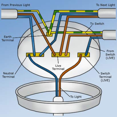
Most smart light switches require a neutral wire. However many UK homes do NOT provide a neutral wire at the switch. A typical UK light switch has a live, switched live and earth only (I.e. no neutral) although there may be confusion as the switched live is commonly blue (or black in older homes) like a neutral would be.
Adding a neutral can be relatively costly as it requires a new cable between the ceiling rose and the switch. If having a re-wire it’s worth adding neutrals to the specification just in case.
Typical ceiling rose wiring UK.
Example automation
Automation.
Both switches or bulbs can be automated via a smart hub for on/off or brightness to respond to time-of-day, movement, door or window opening etc; so that’s not really grounds to chose between smart switches or smart bulbs.
What about combining smart switches and bulbs on the same circuit?
In short I don’t really know why you’d want to. Even if it worked properly you’d have incurred extra cost for the second smart device for limited benefit as you’ve duplicated the smart functions, but it’s likely not to work properly. Even with simple on/off functions the smart bulb will be missed by the hub when the power is off at the switch (although some ecosystems allow this error to be masked), but with dimmers it will probably be worse as the bulb may not function correctly when the dimmer is set to less than 100% brightness.
You might consider using the smart switch as an smart button without using the switched output, and feed the smart bulb from a permanent live, but that’s not combining them on the same circuit. This could be achieved physically by something as simple as moving the switched live output to the live input on a switch. However the two smart devices, switch and bulb, would then need to be linked entirely programmatically through the hub. That would be at least two automations in HomeKIt – an ‘on’ automation and an ‘off’ automation.
Conclusion
There isn’t a right answer whether smart switches or smart bulbs are best. The best choice will depend on your situation.
One of the features of our home is the all-electric kitchen. We do have gas for space heating and as a back-up on the hot water for days that are both dull and have relatively high cost electricity, but the kitchen is all-electric. I have to say that this was not our choice, rather the kitchen came that way when we bought the house five years ago. We have replaced the oven in the meantime, but until today the hob was that bought with the house.
Unfortunately the hob suffered a failure of the two of the rings and today we’ve replaced it like-for-like with a new inductive unit. Inductive is attractive as it’s relatively efficient, but I was struck by the fact that the one hob required a 32 Amp supply, but the new one manages with a 13 Amp plug.
Bosch PUE611BF1B inductive hob.
So, by what magic does the new hob use less than half the power of its predecessor?
item
old hob
New hob
Smallest ring
1,200 Watts
1,400 Watts
Second smallest
1,400 Watts
1,800 Watts
Second largest
1,800 Watts
1,800 Watts
Largest ring
2,200 Watts
2,200 Watts
Total *
6,600 Watts
3,000 Watts
Tabulated of maximum non-Boost power per ring with manufacturer’s total
The first thing to observe is that the sum of the ring powers does not equal the manufacturer’s total for the new hob, although it does for the old hob. The second would be that the sum of the new ring powers at 7,200 Watts is more than the sum of the old ring powers even though the required total is less!
The answer is that the new hob features power management capability. In any hob the rings will spend much of their time cycling on and off to maintain the required heat. In the old hob all the rings might on at one time drawing maximum power, but a few moments later they might all be off. However the power management in the new hob the total power would be levelled out so that the average over time might be the same, but the peaks smaller and the troughs shallower.
For most people this levelling out of the power demand would pass unnoticed, but for us it could be quite useful.
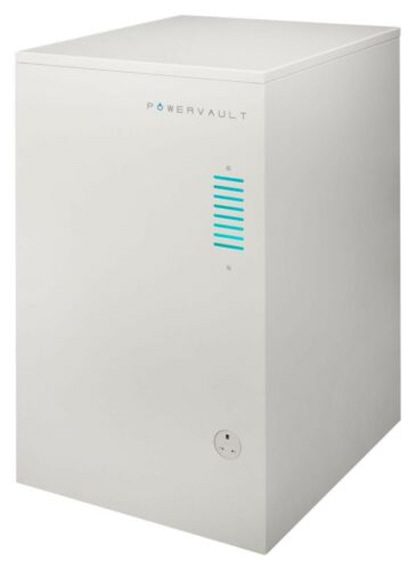
Powervault storage
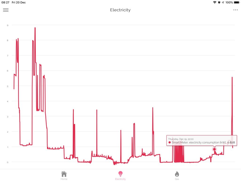
Grid import
We do most of our cooking in the evenings for which, particularly in winter, power is taken from our Powervault storage battery with any excess from the grid as illustrated by the series of evening spikes in the image to the right. The Powervault has a relatively limited maximum power (hence the spikes) but as the new hob has power management then any spiking beyond battery maximum power capability should be reduced thus avoiding what, for us, could be peak rate electricity at 35 p/kWh on our dynamic smart tariff which is a direct cost save.
Well, it had to happen. After thirteen-and-a-half years of ownership of a plug-in vehicle we’re about to have two. I have had two briefly before during a vehicle changeover having bought a new one and then sold the old one privately, but now we’re replacing the hybrid that my wife generally drives with a plug-in hybrid. Not only will that give us two plug-in vehicles, but in the six years that I’ve owned the Ampera the standard inlet connector has changed from 5 pins to 7 pins so I can’t charge the new car on my existing smart charger either.
Stepped Mode 3 EVSE in consumer unit case
Most people of course will be content with an off-the-shelf charger, but I had some fairly uniquely requirements. One of the requirements that influenced my original charger was solar self-consumption (the charger automatically turns on when the home is in sufficient solar surplus) but this is now available commercially. My existing charger also adjusts its charge times around the Agile electricity tariff but this too is now available commercially with Ohme. However I still want to be able to coordinate it all centrally via my HEMS so that I can prioritise loads when constrained, or enable interactions like stopping the fixed battery discharging into the car at night and that’s not available commercially.
My solution is similar, but different, to my old charger. Both are modified from existing production chargers as a relatively affordable source of parts, but the new one will retain the production case (because it needs to be waterproof for outdoor use) and be better protected electrically than the old one. It needs to be better protected as electrical standards have moved on and, being outdoors, it needs to be more sophisticated to make up for the UK’s somewhat unusual earthing system (at least by international standards). It will also be smarter, but that will be described in later posts.
Commercial Mode 3 EVSE
Commercial Mode 3 EVSE – 2nd donor
Donors for first and second Smart EVSE.
The most common earthing system in the UK involves a cable between the home and the substation called a Protective Earth Neutral (PEN) conductor which, as its name implies, provides both the neutral and earth on a single core. Remember PEN as it will come up later..
My new charger will also be higher power than the old one. The old one is designed for 10 Amps continuous grid load (16 Amps peak from solar) based on the limitations of my garage supply, but the new one is designed for 32 Amps continuous load in anticipation of a future fully-electric vehicle. I have owned a fully electric vehicle previously, but for the moment both our vehicles will be plug-in hybrids. Some would argue the case for one being an Extended-Range Electric Vehicle (E-REV) or Range-EXtended Battery Electric Vehicle (REX BEV).
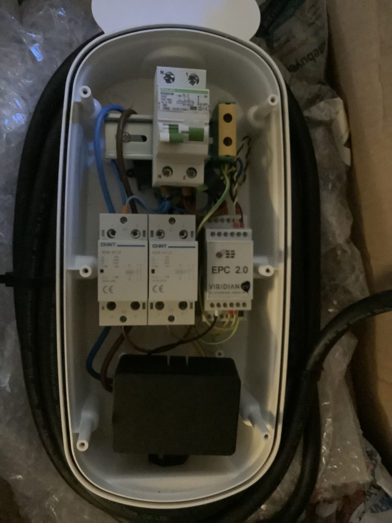
Similar production charger
My updated charger (work in progress)
Inside donor and modified EVSE.
The two internal pictures above show a similar production charger alongside my updated charger. The differences are (from top to bottom):
RCBO (combines over-current and residual current detection) – is actually carried over donor, but my charger came with a later model than the similar charger illustrated.
Earth terminal – I relocated from centre middle row to right top row to make space.
Residual Current Monitor (RCM) – The RCM (a small black box which encircles the live and neutral) sits behind the RCBO and triggers shutdown in the event of a D.C. fault.
PEN Loss Current Transformer – between the top and middle rails a small black ring sits around the earth cable. This is similar in principle to the RCM but rather than detect a D.C. fault on the supply, its role is to detect a fault current to earth. That’s not enough alone to provide PEN-loss detection alone but provides additional detection to that in the Protocol Controller (which we’ll get to soon).
Power contactor. The second rail starts on the left with a power contactor which disconnects the live and the neutral from the car when not charging. Mine is similar to the Rolec original, but smaller,
Switched Protective Earth (SPE) contactor. In the centre of the unit sits a second similar contactor, only this one switches the earth. Switching an earth is unusual but is required to protect against a failure of the PEN conductor between home and substation. The power contactor will not close and the car will not charge if the SPE is open with the result that the car is completely isolated from the mains supply during this failure mode.
Protocol controller. To the right of the centre rail is the protocol controller. This replaces the the original protocol controller which was in a similar position. The fundamental need to change was driven by the requirement to vary the charge current dynamically, but the new protocol controller also monitors not only the two current transformers (RCM and PEN-loss) but also the supply voltage in order to decide when to open the SPE contactor.
Raspberry Pi. At the bottom is an empty Raspberry Pi case to illustrate the sufficient space is available. The actual Raspberry Pi will be smaller. The role of the Pi is to tell the protocol controller how much current should be drawn. The Pi will tell the protocol controller via an analogue voltage, and the protocol controller will tell the car via a Pulse Width Modulated (PWM) signal – that is the width of a stream of voltage pulse indicates the current that the car should draw. The replaces the Programmable Logic Controller (PLC) and RF Solutions radio link in my older smart charger.
LED leads. At the very bottom 4 leads with red connectors leave the picture on the left which go to an external multicolour LED for charger status. I haven’t yet decided how to reproduce this. The donor LED is unsuitable as it only has three colours (Red, Green and Blue) but the protocol controller assumes that two further colours (white and purple) are also available,
Item
My original smart charger
New donor
My New smart charger
Switch
Double pole
+ RCBO
c/o from donor
RCM CT
No
No
New
PEN-loss CT
No
No
New
Power contactor
Yes
Yes
Yes
SPE contactor
No
No
Yes
Protocol controller
Viridian v1.0 (variable current)
Rolec (fixed current)
Viridian v2.0 (variable current with extra safety content)
Smart controller
Programmable Logic Controller (PLC)
No
Raspberry Pi
External communications
Radio (RF Solutions)
No
Wi-Fi (Part of Pi)
Status LED
LED on protocol controller visible through clear cover.
External LED. No LED on protocol controller.
External TBD. LED on protocol controller (not visible).
Comparison. between my existing smart charger, new donor, and new smart charger.
The new hardware will thus shutdown in the event of the following faults:
Over-current
Residual current (live – neutral)
DC current *
Earth leakage current *
Over-voltage *
Under-voltage *
Inferred PEN loss *
Lack of earth continuity between vehicle and wallbox
* These are additional protections in my new hardware that weren’t present in the old one.
At this point I should have a working dumb charger with 32 Amp capability, albeit that it’s untested as yet through lack of a compatible vehicle with a Type 2 vehicle inlet.
There are two items for which I’m awaiting delivery. Firstly I’ll be using a Raspberry Pi Zero to generate the current demand signal which will replace the empty black case in the picture and secondly I have a small 5V power supply on order to power that Pi.
Future posts will look at adding the smart controls.